Seleccionar página
Technical Deep-Dive · Industrial Power Transmission

How Roller Chain Performs Under
Shock Load and Reverse Drive Condiciones

Published by Ever Power Engineering · UK Edition · Updated 2026

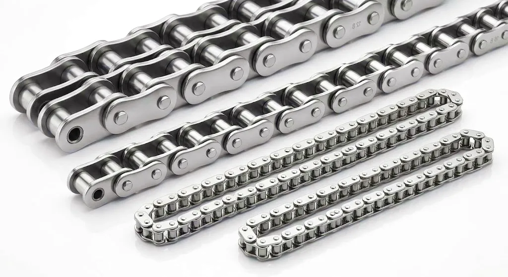
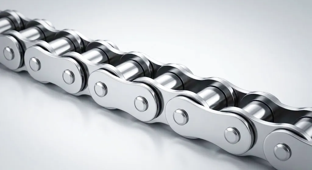
Roller chain assembly used in heavy industrial application

Roller chain is one of the most reliable and widely deployed mechanical transmission components in existence — yet its behaviour under shock load and reverse drive is often misunderstood, underestimated, or entirely overlooked at the design stage. In heavy industries across the United Kingdom, from the steelworks of Sheffield to the automotive production lines in Birmingham and the port logistics facilities along the Humber Estuary, roller chain operates in environments where power reversals, sudden load spikes, and vibration are daily realities rather than exceptional events. When a chain is selected purely on rated tensile strength without accounting for dynamic duty, premature failure becomes almost inevitable.

Understanding how roller chain actually responds to shock loading — the physics of energy absorption, the metallurgical demands placed on pins and plates, the role of lubrication under high-frequency stress — gives engineers and procurement professionals the knowledge they need to specify correctly, extend service intervals, and reduce unplanned downtime. Reverse drive adds a further layer of complexity: the chain must manage the transition from slack-side tension to drive-side tension and back again without inducing destructive backlash or polygon effect amplification. This article examines every dimension of that challenge in technical detail.

Working Principle: How Roller Chain Transmits Power

⚙️
Engagement Geometry

A roller chain transmits torque through the mechanical engagement of hardened rollers with sprocket teeth. As each roller seats into a tooth gap, the normal force from the sprocket flank pushes the chain forward. The rollers are free to rotate independently on their bushings, which means the primary contact stress transforms from sliding friction into rolling friction — dramatically reducing wear rates compared to flat-link or toothed belt systems. Under nominal operating conditions, this geometry is well understood. Under shock loading, however, the seating dynamics become far more violent, and the impact energy that each roller must absorb during engagement increases by a factor proportional to the square of the speed ratio deviation.

📐
Polygon Effect Explained

The so-called polygon effect arises because a chain wrapping around a sprocket does not follow a perfect circular arc — it follows a series of chords. This produces a cyclic variation in chain velocity and a corresponding tension fluctuation even under perfectly steady motor input. The magnitude of this effect scales inversely with sprocket tooth count: a 9-tooth sprocket induces velocity variation of roughly 6%, while a 25-tooth sprocket reduces it to under 0.8%. Under reverse drive conditions, the polygon effect is encountered in both rotational directions, meaning the system must manage two distinct tension-fluctuation cycles per revolution, effectively doubling the fatigue stress amplitude on link plates and pins compared to unidirectional drive.

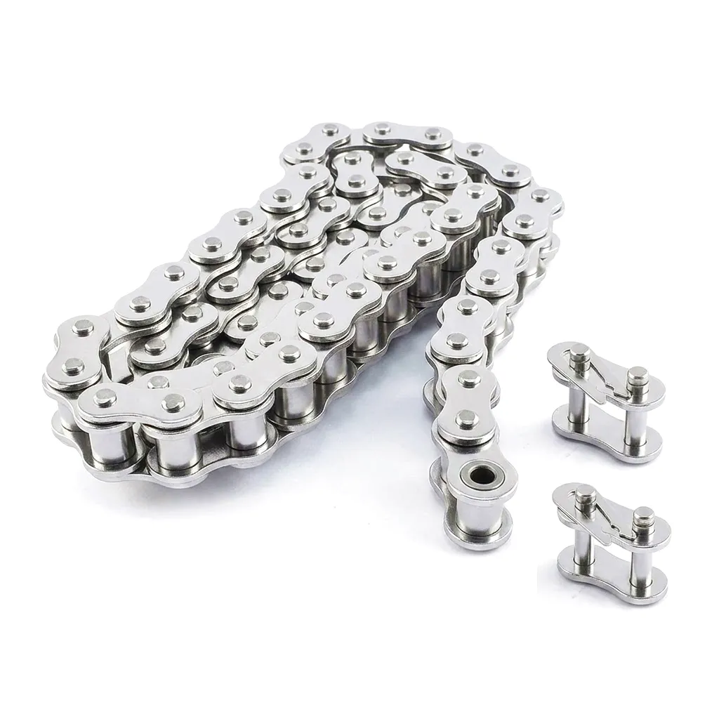
Precision manufactured roller chain for industrial transmission

The energy pathway inside a roller chain during shock loading follows a specific sequence that every design engineer must appreciate. When an external shock impulse — say, a jammed conveyor suddenly releasing, or a vehicle powertrain engaging at high speed — arrives at the drive sprocket, the kinetic energy is distributed first through the tight-side strand as a tensile pulse. The pins and bushings must absorb this pulse within the elastic range of the steel; if the peak stress exceeds the material’s fatigue limit at that instant, micro-crack initiation begins at the pin surface, typically near the inner plate press-fit region.

What differentiates a high-quality roller chain from a commodity one is the relationship between case hardness depth, core ductility, and the precision of the pin-to-bushing clearance. A properly manufactured roller chain maintains a thin, hard case (typically HRC 58–62 on pins) over a tough, medium-carbon core that can yield plastically before fracturing. This combination means that shock pulses which exceed the elastic threshold cause controlled localised deformation rather than sudden brittle fracture — a critical distinction in safety-critical British manufacturing operations where unexpected chain failure can halt entire production lines.

Core Materials: Metallurgical Choices That Define Performance

Material selection in roller chain manufacture is far more nuanced than simply choosing “alloy steel.” The performance envelope under shock load and reverse drive is determined by at least four distinct material grades, each engineered to fulfil a specific mechanical role within the chain assembly. Getting any one of them wrong compounds failure modes across the entire component.

🔩 Pins — Chromium-Molybdenum Steel

Pins are manufactured from chromium-molybdenum alloy steel (typically 20CrMo or equivalent to EN 1.7218), carburised to achieve a case hardness of HRC 58–62 with a case depth of 0.4–0.8 mm. The chromium content improves hardenability and wear resistance; the molybdenum suppresses temper brittleness and maintains toughness at elevated operating temperatures. Under repeated shock loading, the pin’s fatigue behaviour is dominated by the press-fit stress concentration at the inner plate bore — this is why dimensional tolerance at this interface is held to within ±0.005 mm in quality manufacture.

🔗 Bushings — Low-Carbon Alloy Steel

Bushings bear the oscillating contact stress between pin and roller simultaneously. They are manufactured from low-carbon alloy steel with a carburised surface of HRC 54–60, but critically with a case depth slightly shallower than the pin — this creates a controlled hardness gradient at the pin-bushing interface that allows micro-elastic conformance under high loads rather than galling. During reverse drive, the relative motion direction between pin and bushing reverses, and the thin lubricant film must reform in a new orientation; bushings with poor surface finish trap contaminants during this transition and initiate fretting wear within a few hundred reverse cycles.

🛡️ Link Plates — Medium-Carbon Steel

Inner and outer link plates are stamped from medium-carbon steel strip (0.35–0.55% C), then heat-treated to a bulk hardness of HRC 35–45. The plate geometry — specifically the waist radius at the pin hole — is a critical fatigue site. During shock loading, the stress concentration factor at this waist can reach 2.8–3.5 times the nominal stress. Quality manufacturers use precision blanking and shot-peening to introduce compressive residual stresses at the plate surface, which raise the effective fatigue limit by 15–25% and significantly extend the chain’s useful life in applications subject to frequent shock events, as seen in Birmingham’s automotive stamping operations.

⚪ Rollers — High-Carbon Chromium Bearing Steel

Rollers are typically manufactured from high-carbon chromium steel (equivalent to EN 31 or 100Cr6), through-hardened to HRC 60–64. This is the component that experiences the most severe impact loading during sprocket engagement — each meshing event is essentially a Hertzian contact problem with a dynamic component. The roller’s through-hardened structure means it has no soft core, which is appropriate because the loading is compressive rather than bending-dominant. In heavy shock applications, some manufacturers offer enlarged-roller variants that increase the contact area and reduce peak Hertzian stress, extending service life by 30–50% compared to standard-diameter rollers at the same chain pitch.

Shock Load Performance: Physics, Failure Modes and Industry Practice
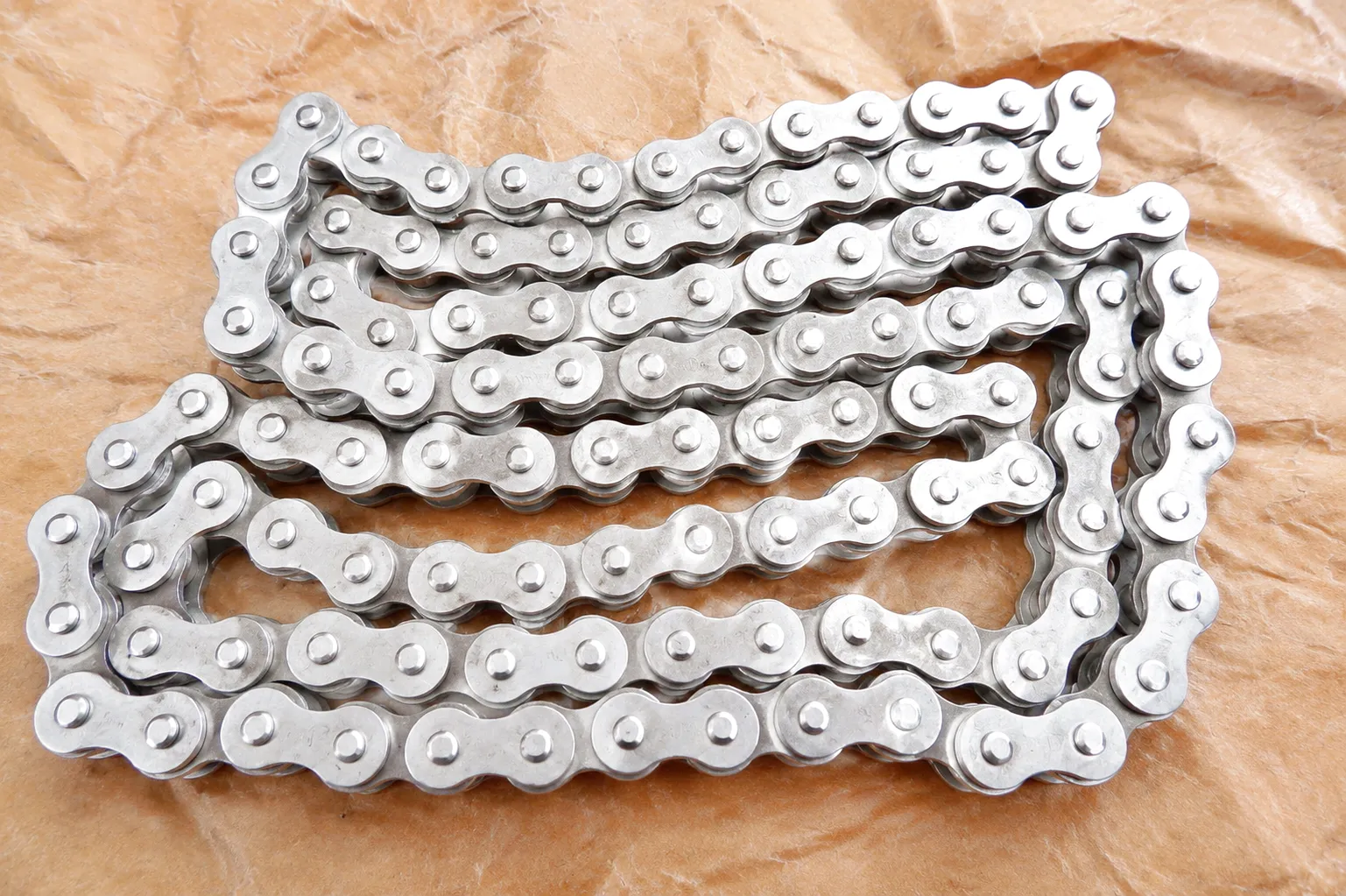
High-strength roller chain under industrial shock load conditions

Shock loading in chain drive applications is quantified through the service factor approach defined in ISO 10823 and its British equivalent. A service factor of 1.0 applies to smooth, steady loads — electric motors driving centrifugal pumps, for example. As duty becomes more impulsive, the service factor rises: light shock (1.0–1.3), moderate shock (1.3–1.5), and heavy shock (1.5–2.0 or higher). In practical terms, this means the chain must be selected at 1.5 to 2 times the calculated working load for applications such as crushers, reciprocating compressors, and presses — equipment that is ubiquitous in Sheffield’s steel processing facilities and in the heavy fabrication yards along the River Tyne.

The three primary failure modes under shock loading are: link plate fatigue fracture, pin shear, and roller spalling. Plate fatigue typically initiates at the pin-hole bore due to stress concentration and the fretting that occurs during each load-oscillation cycle at the press-fit interface. Pin shear is less common in modern alloy-steel chains but occurs in under-specified applications where the instantaneous shear stress across the pin cross-section exceeds the material’s ultimate shear strength — a condition that can occur in a single severe shock event rather than accumulating over many cycles. Roller spalling follows a Hertzian contact fatigue mechanism analogous to bearing failure, with characteristic shallow pitting appearing on the roller’s outer diameter after extended exposure to high cyclic contact stresses.

Mitigation strategies are well established. The most effective single measure is increasing the sprocket tooth count: moving from a 17-tooth to a 23-tooth drive sprocket reduces the polygon effect velocity variation by approximately 40%, which directly reduces the dynamic tension amplitude superimposed on the static working load. Lubrication strategy is equally critical — under shock loading, the elastohydrodynamic film between pin and bushing must reform rapidly after each shock event; ISO VG 100–150 oils with anti-wear additives are typically specified for this duty, and some operators in UK mining and quarrying applications use grease-lubricated sealed chains where external contamination is unavoidable.

🔗 Featured Product
Cadena de rodillos de alta resistencia 120HSP-00 para Caterpillar

Engineered for Caterpillar machinery operating in severe shock environments. Features enhanced pin case depth and precision-ground link plates for maximum fatigue resistance in UK heavy equipment applications.

Ver producto →


🔗 Featured Product
Cadena de rodillos de alta resistencia C100HSP-00 para Caterpillar

A heavy-duty variant with extended bushing contact length and premium alloy pin material, ideal for continuous reverse-drive duties in UK construction and mining fleet maintenance.

Ver producto →

Reverse Drive Conditions: Engineering Challenges and Solutions
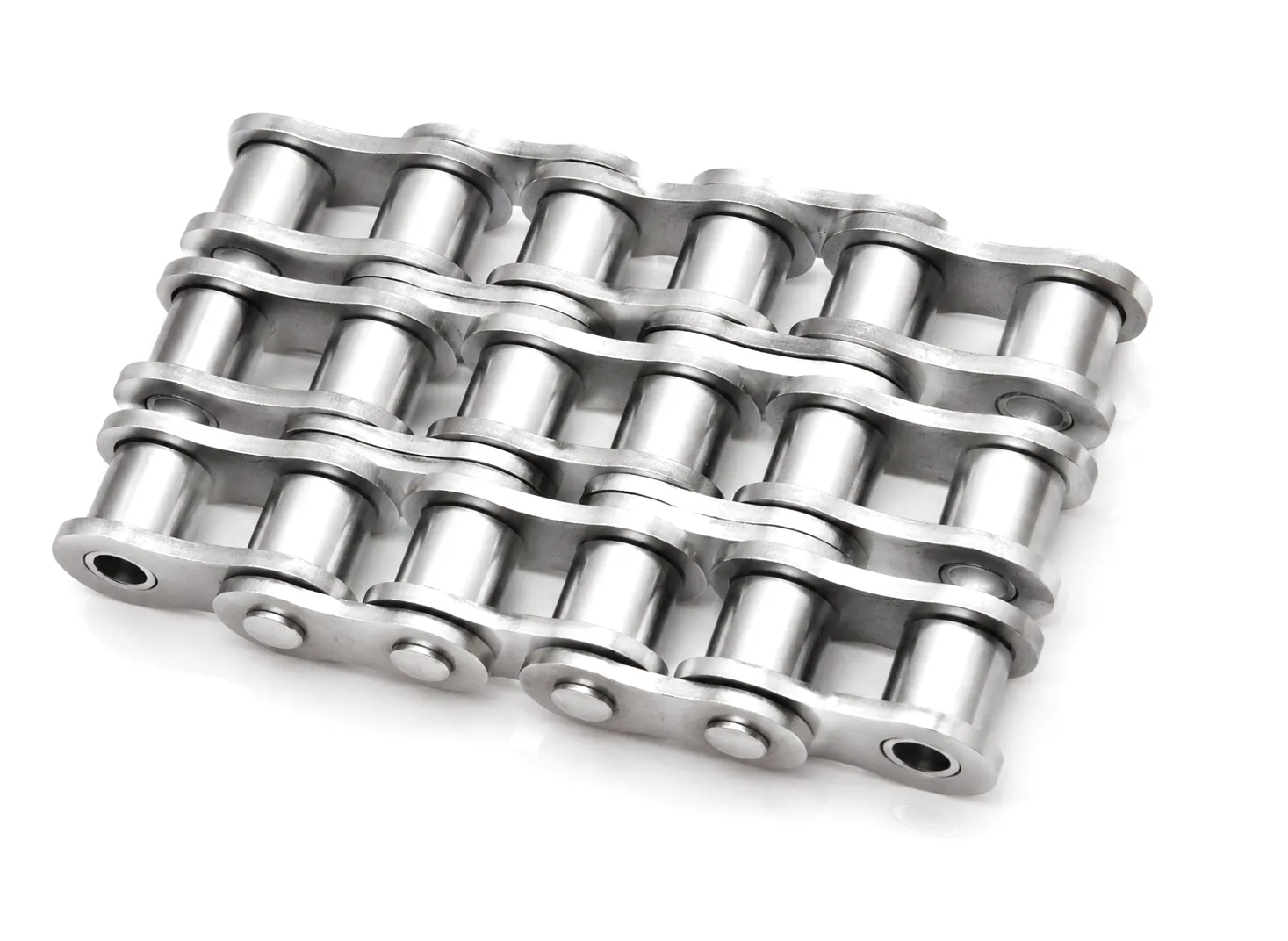
Roller chain reverse drive sprocket engagement industrial

Reverse drive — where the chain must transmit power in both rotational directions — is encountered in a surprisingly wide range of industrial applications: crane hoists, winch systems, reversing conveyor installations, and many CNC machine tool axis drives. What makes reverse drive mechanically demanding is not the reversal itself but the transition period between the two drive directions. During this interval, the tension distribution in the chain changes completely: the tight side becomes slack and vice versa. If the chain’s sag on the previously tight side is significant, the chain can momentarily run slack and then re-tension with a sharp impulse — effectively a self-induced shock load that is superimposed on whatever external shock the application already generates.

One frequently overlooked consequence of reverse drive is the accelerated wear of the sprocket tooth flanks. Under unidirectional drive, only one flank of each sprocket tooth experiences significant contact stress. Under bidirectional drive, both flanks wear simultaneously, and the asymmetric load-sharing that typically compensates for tooth form errors under unidirectional operation no longer applies. The result is that sprocket service life in reverse-drive applications can be 40–60% shorter than in equivalent unidirectional installations, which has direct implications for total cost of ownership calculations in UK manufacturing and materials handling operations.

Designers addressing reverse-drive applications should increase both chain pitch size and sprocket tooth count beyond what nominal power calculations would suggest. A chain catenary tension pre-load device — essentially a spring-loaded idler — is highly effective at maintaining positive chain tension during the direction-reversal interval, preventing the catastrophic snap-tensioning that causes rapid joint fatigue. Where space constraints preclude an idler, specifying a chain with a reduced clearance joint assembly (sometimes called a precision-fit or HRC designation chain) limits the free play within each link joint and narrows the deformation amplitude during the slack-to-tight transition.

Parámetros técnicos y de rendimiento del producto

The table below consolidates the key technical parameters relevant to roller chain selection for shock load and reverse drive applications. Values represent typical ranges for standard-pitch industrial chains manufactured to ISO 606 / BS ISO 606 specification; heavy-duty variants and custom-specification chains from Ever Power may exceed these figures.

Parámetro Standard Chain Heavy-Duty / HSP Unit
Rango de tono 6.35 – 101.6 12.7 – 101.6 mm
Minimum Tensile Strength 8.9 – 400 14.1 – 500+ kN
Recommended Working Load 1/7 of MTS 1/6 of MTS Safety factor
Pin Hardness (Surface) HRC 58 – 62 HRC 60 – 64 Rockwell C
Case Depth (Pin) 0.4 – 0.7 0.6 – 0.9 mm
Roller Hardness HRC 60 – 64 HRC 62 – 66 Rockwell C
Max Operating Speed Up to 3,000 Up to 2,500 rpm (drive sprocket)
Service Temperature Range -10 to +150 -20 to +200 °C
Shock Service Factor 1.0 – 1.5 1.5 – 2.0+ Multiplier on rated load
Applicable Standard ISO 606 / BS ISO 606 ISO 606 + custom spec
Elongation Limit (Replacement) 3% 2% (shock applications) % of nominal length

Core Technical Advantages of Industrial Roller Chain

💪
High Shock Absorption Capacity

The multi-jointed structure of roller chain inherently distributes shock energy across dozens of link joints simultaneously, making it far more resilient to sudden impact loads than rigid couplings or toothed belts, which must concentrate the same energy in a single engagement zone.

🔄
Bidirectional Drive Compatibility

Unlike V-belts or flat belts, which experience significant slip and tension loss during direction reversal, roller chain maintains positive mechanical engagement throughout the reverse transition. Properly designed roller chain drives can achieve reverse-drive efficiencies exceeding 96%, comparable to forward-drive performance in most applications.

📏
Precise Centre-Distance Flexibility

Roller chain can operate across a wide range of shaft centre distances — from very close-coupled arrangements to extended runs of several metres — without the preload or tensioning constraints that limit synchronous belt drives. This flexibility is particularly valuable in the large-scale plant engineering found in UK chemical processing facilities.

🌡️
Wide Temperature Operating Range

Alloy steel roller chain retains its mechanical properties across a temperature range of -20°C to 200°C in standard grades, and up to 450°C in nickel-plated or stainless-steel variants. This makes roller chain the preferred solution in UK foundry environments and food-processing facilities where temperature extremes are part of normal operations.

Alta densidad de potencia

Roller chain achieves a power-to-weight ratio that significantly exceeds V-belt drives at equivalent pitch sizes, particularly at lower speeds where belt drives suffer from stiffness losses. A single strand of 1″ pitch chain can routinely handle 15–25 kW of transmitted power in light shock applications, rising to over 100 kW with multi-strand assemblies.

🔧
Straightforward Maintenance and Length Adjustment

Unlike most alternative power transmission technologies, roller chain length can be adjusted in the field by adding or removing links, without requiring specialist tooling or complete system disassembly. This translates to substantially reduced maintenance downtime in UK industrial sites where minimising production stoppages is a primary operational priority.

Industrial Application Scenarios: Where Shock and Reverse Drive Conditions Demand Careful Chain Selection
🏗️ Construction and Mining Equipment — Sheffield, South Yorkshire

Excavators, drilling rigs, and aggregate crushers operating in and around Sheffield’s quarrying and civil engineering sector represent one of the most demanding roller chain environments in British industry. The drive chains on jaw crusher flywheels and feed conveyors are subjected to repeated shock loads every time a rock fragment of inconsistent hardness passes through the crusher chamber. These applications routinely see instantaneous peak tensions four to six times the mean running load. High-strength roller chain in 1.5″ to 2″ pitch with enhanced case depths on pins and shot-peened link plates is the standard specification for this duty. Service intervals in these applications are typically set at 2,000–3,000 hours rather than the 8,000+ hours possible in smooth-duty installations.

🚗 Automotive Manufacturing — Birmingham, West Midlands

Birmingham’s automotive supply chain includes numerous press shops, transfer line facilities, and assembly operations where roller chain is used in conveyor indexing systems, robotic arm actuators, and press brake drives. The indexing conveyors that position body panels under welding robots operate in a start-stop mode that creates recurring shock events at every indexing cycle — potentially 200,000 to 500,000 cycles per year per chain strand. For these applications, the use of precision offset link assemblies and specialised self-lubricating chain variants has become standard practice, reducing manual lubrication frequency while maintaining the hydrodynamic film integrity needed under shock loading. Ever Power supplies several Birmingham-area Tier 1 automotive suppliers with custom-length, precision-assembled roller chain to exacting OEM specifications.

⚓ Port and Marine Logistics — Humber Estuary, Humberside

The port facilities along the Humber Estuary — one of the UK’s most active freight gateways — rely on roller chain in ship-to-shore crane hoisting mechanisms, stacker-reclaimer drives, and roll-on/roll-off vessel ramp actuators. These are prime examples of applications combining both shock loading and reverse drive: a crane hoist must accelerate a load, travel, and then lower it under controlled braking, with the chain drive experiencing full load reversal at each cycle. The salt-laden marine atmosphere also demands corrosion-resistant chain variants, including nickel-plated or stainless-steel options. Specifying chain with sealed joints prevents ingress of the fine saline particulate that otherwise accelerates fretting corrosion at the pin-bushing interface within weeks of installation.

🏭 Steel and Metals Processing — Middlesbrough, Teesside

Rolling mills, continuous casting lines, and slab handling systems in Teesside’s steel sector use roller chain for table roll drives and slab transfer systems where operational temperatures can exceed 150°C and scale contamination is constant. The reversing transfers used to position billets and slabs are classic high-shock, reverse-drive applications. Scale particles — hard iron oxides — are among the most abrasive contaminants a chain joint can encounter, accelerating bushing-to-pin wear at several times the rate seen in clean environments. Specifying chain with oversized pins and heavy-duty link plates, combined with a proactive scheduled replacement programme, is the standard approach among Teesside operators to manage maintenance costs on these critical production assets.

🌿 Agricultural Machinery — Lincolnshire and East Yorkshire

Combine harvesters, grain dryers, and root crop processing machinery operating in Lincolnshire’s expansive arable farming zone rely on roller chain for threshing drum drives, elevator chains, and header auger drives. Agricultural duty combines heavy shock loading — when stone or soil is ingested through the header — with frequent reversal during blockage clearing procedures. Blockage events can generate peak tensile loads five to eight times higher than normal operating tension in a fraction of a second, making agricultural roller chain applications arguably the most demanding shock environment in UK industry. Overload clutches are standard in these drivetrains, but the chain itself must also have sufficient ductile reserve to survive the occasional event that exceeds the clutch response time.

🏗️ CNC Machine Tools and Precision Manufacturing — Coventry, West Midlands

Coventry remains a significant centre for precision engineering and CNC machine tool manufacture. Linear axis drives in large machining centres and pallet changers frequently use roller chain for the final linear motion element, particularly on heavy-duty five-axis machines where the table can exceed 5,000 kg. In these applications, the combination of extremely tight positional accuracy requirements and the inherent shock loading that occurs when the axis changes direction at high traverse speeds demands that the roller chain system achieves both high fatigue strength and minimal joint clearance. Precision-pitch roller chain to ISO 606 Class A tolerances, combined with pre-tensioned installation and a dedicated chain guide system, is the specification approach adopted by leading UK machine tool builders.

Roller chain detail showing roller and bushing engagement
Industrial roller chain in conveyor application
Close-up of hardened roller chain pins and link plates

Manufacturer Spotlight

Ever Power: Fabricación de precisión y soluciones personalizadas para cadenas de rodillos.

Ever Power operates one of the most technically advanced roller chain manufacturing facilities in Asia, supplying British industry and global markets with chains engineered to exceed standard specification requirements in shock load and reverse drive applications. The manufacturing operation centres on a fully integrated production line — from raw steel selection and heat treatment through precision grinding of pin and bushing diameters, link plate blanking, assembly, and final quality verification — that allows total control over every variable that determines performance under dynamic loading.

Customisation at Ever Power is a core competency, not an afterthought. UK buyers requiring non-standard pitch lengths, extended attachment plates for conveyor systems, modified link plate geometries for bespoke machine designs, or coating systems for corrosive environments are accommodated through a structured customisation process that begins with detailed application analysis. Our engineering team reviews customer-supplied data on shock factor, reversal frequency, environmental conditions, and existing failure modes to recommend the optimal chain specification — often identifying design improvements that extend service life by 50% or more compared to the off-the-shelf chains previously used.

Supply chain reliability is built into the Ever Power model. Stocked inventory of the most common UK-market chain standards enables short-lead dispatches to British buyers, while bespoke orders are manufactured to agreed schedules with production milestones communicated transparently throughout. All chains are shipped with full material certification and dimensional inspection reports, meeting the documentation requirements of UK industrial procurement standards and supporting BSI-aligned quality management systems at customer facilities.

Manufacturing Capabilities
ISO 606 / ANSI B29.1 compliant production
Custom pitch and extended pin designs
Enhanced case depth (up to 0.9 mm)
Shot-peened link plate option
Nickel, zinc, or anti-corrosion coatings
Pre-lubricated and sealed joint variants
Full material certs and inspection reports
Fast despatch to UK buyers

Customer Success Story: Aggregate Processing in Leeds, West Yorkshire

Fondo

A medium-sized aggregate processing company operating a crushing and screening plant on the outskirts of Leeds, West Yorkshire had been experiencing roller chain failures on their primary jaw crusher drive at unacceptably high frequency — on average, one chain failure every four to six weeks across two crusher units. Each failure resulted in approximately six hours of unplanned downtime, including diagnosis, parts procurement from local distributors, and re-assembly. At a conservative estimate of £2,800 per hour of lost production, the annual cost of chain-related downtime exceeded £250,000 — not including the cost of replacement chains and labour. The plant manager engaged Ever Power following a referral from a plant equipment supplier in the Leeds area.

Problem Analysis

Ever Power’s application engineering team reviewed the failed chains and the crusher drive specification. The existing chain was a standard 1.5″ pitch roller chain specified to the minimum tensile strength required by nominal power calculations, with no additional service factor applied for shock loading. Link plate fatigue fractures, predominantly at the pin-hole bore, accounted for over 80% of failures — a clear indication that the dynamic stress amplitude was consistently exceeding the fatigue limit of the plate material. Pin wear was also elevated, suggesting that the lubrication interval had not kept pace with the actual duty cycle, which was running at approximately 1.4 times the speed assumed in the original design calculation due to a drive pulley change made during a previous motor upgrade. Crucially, the jaw crusher’s heavy flywheel meant that a blocked-feed event did not simply stall the chain — it delivered a massive stored kinetic energy impulse to the chain during the subsequent flywheel discharge, creating peak loads calculated to be in excess of 8 times the mean running load.

Ever Power Solution

Ever Power specified a custom heavy-duty roller chain in 1.5″ pitch with the following enhancements over the standard product: link plates manufactured from premium-grade medium-carbon steel with shot-peened surfaces to introduce a compressive residual stress layer; pins with an extended case depth of 0.85 mm and a peak hardness of HRC 63; bushings with a refined surface finish of Ra 0.4 µm to optimise the pin-bushing lubricant film under rapid load reversals; and an overall minimum tensile strength rating 35% above the ISO 606 standard for that pitch. The drive was also redesigned with an increased drive sprocket from 17 teeth to 21 teeth, reducing the polygon effect velocity variation from 5.2% to 2.8% and thereby cutting the dynamic tension amplitude by approximately 46%. A sealed idler tensioner was installed to maintain positive chain tension during the frequent shock events.

Results Achieved

Following installation on both crusher units, the Leeds facility ran for 22 consecutive weeks without a single chain failure — a performance improvement of over 400% compared to the pre-Ever Power baseline. When the first chain was eventually replaced at a planned maintenance interval, inspection showed that link plate wear was within acceptable limits and pin surface condition remained well within serviceable range. The second chain set ran to 28 weeks before planned replacement. The plant manager reported a reduction in chain-related maintenance costs of approximately 78% in the first operating year following the Ever Power specification change, with unplanned downtime associated with chain failure effectively eliminated.

★★★★★

“We had tried two other chain suppliers before Ever Power and kept getting the same failure pattern. The Ever Power team actually analysed our failed chains and redesigned the drive rather than just selling us another chain. The difference in service life has been night and day — we haven’t had an unplanned stoppage from chain failure in over six months.”

— Plant Manager, Aggregate Processing Facility, Leeds, West Yorkshire
★★★★★

“The custom chain Ever Power made for our reversing conveyor system was exactly what the specification required. We run this system in both directions multiple times per hour and the previous chains were elongating to replacement threshold within two months. The Ever Power heavy-duty variant has held dimensional tolerance for going on five months now with no signs of accelerated wear on the pin surfaces.”

— Maintenance Engineer, Materials Handling Company, Birmingham, West Midlands
★★★★★

“Procurement documentation, material certificates, dimensional inspection reports — Ever Power provided everything our quality assurance team required for supplier qualification without us having to chase for it. The technical support during the application review was thorough and genuinely improved our understanding of why we had been seeing premature chain failures. A supplier that brings engineering value, not just product supply.”

— Procurement Director, Precision Engineering Group, Sheffield, South Yorkshire

Preguntas frecuentes

How does roller chain actually perform differently under shock load conditions compared to normal operating loads in UK industrial environments?

Under shock loading, the instantaneous tension in the chain can reach three to eight times the mean running load, depending on the severity of the impulse. This dramatically increases the stress at critical points — primarily the pin-hole bore in link plates and the pin-bushing interface — often exceeding the fatigue limit of the material within a relatively small number of cycles. In contrast, under normal steady operating loads, roller chain can run for tens of millions of cycles before fatigue damage accumulates to failure threshold. In UK industrial environments, where drives are often not reviewed after initial commissioning, the shock factor is frequently underestimated, leading to premature failures that are misdiagnosed as product quality issues rather than specification problems.

What is the typical price difference between a standard roller chain and a heavy-duty shock-rated roller chain, and is the extra cost worth it for a Birmingham manufacturing facility?

Heavy-duty shock-rated roller chain typically costs 25–50% more than equivalent-pitch standard chain, depending on the specific enhancements specified — deeper case depths, shot-peened plates, precision-fit joints. However, the total cost of ownership equation almost always favours the heavy-duty option in genuine shock applications. A standard chain failing every 6–8 weeks means multiple replacement costs per year plus the downtime. A heavy-duty chain running for 24–36 weeks before replacement, even at higher unit price, reduces total annual chain spend while essentially eliminating the downtime cost component. For Birmingham manufacturing facilities with high production value per operating hour, the case for heavy-duty specification is compelling.

Which UK industries most commonly experience roller chain failure due to reverse drive conditions, and what are the most effective ways to extend chain service life in those applications?

The UK industries with highest incidence of roller chain failure specifically attributable to reverse drive are crane and hoist manufacture (particularly in the port logistics sector around Humberside and Teesside), CNC machine tool production in Coventry and West Yorkshire, and materials handling system integrators serving e-commerce distribution centres. The most effective service life extensions come from: increasing drive sprocket tooth count to reduce polygon effect, installing spring-loaded idler tensioners to prevent snap-tensioning during reversal, specifying precision-fit joint assemblies with reduced clearance to limit deformation amplitude, and switching from periodic oil-bath lubrication to drip-feed or automatic lubrication systems that maintain film integrity through every direction reversal.

How do I get a quote from a reputable roller chain supplier in the UK for a custom heavy-duty chain specification for my Sheffield engineering plant?

To obtain a technically valid quote for custom heavy-duty roller chain, you should prepare a brief application data sheet covering: chain pitch required, drive power (kW) and speed (rpm), driven machine type and estimated shock factor, environmental conditions (temperature, contaminants), current chain failure mode if applicable, and any specific material or coating requirements. Submitting this information to [email protected] will allow Ever Power’s engineering team to review your application and return a specification recommendation alongside pricing within two to three business days. This process is free of charge and carries no obligation to purchase.

When should a UK plant engineer replace a roller chain that operates under heavy shock load, and what are the key signs that replacement cannot be safely deferred any longer?

The primary replacement trigger for roller chain in heavy shock applications is elongation reaching 2% of nominal pitch length — lower than the 3% threshold used for smooth-duty chains, because the higher stress amplitude means fatigue damage accumulates faster once wear elongation begins. Secondary indicators include visible wear marks on the roller outer diameter (indicating sub-optimal lubrication or excessive sprocket contact stress), side-plate discolouration from heat generated by friction (indicating insufficient lubrication), and audible roughness or rattling during operation that was not present when new. In shock environments, do not wait for visible plate cracking before replacement — by the time a crack is visible on a link plate surface, the chain is operating on borrowed time.

Where can a mining or quarrying operation near Leeds find a reliable supplier for high-strength roller chain with fast delivery and proper material certification for BS ISO 606 compliance?

Ever Power supplies high-strength roller chain direct to UK buyers including quarrying and mining operations in the Yorkshire and Derbyshire Peak District area. Standard-specification BS ISO 606 compliant chains in common pitches are held in production-ready inventory for rapid order processing and international despatch. Custom specifications — including the enhanced case depth and shot-peened plate options suited to quarrying shock environments — are manufactured to order with typical lead times of three to five weeks, and all shipments are accompanied by material certification (mill certificates for pin and plate steel), dimensional inspection reports, and hardness verification data. Contact [email protected] with your requirement for an immediate response.

Specify with Confidence. Source with Certainty.

Contact Ever Power’s engineering team today for technical support, application analysis, and competitive pricing on roller chain solutions engineered for the UK’s most demanding industrial environments.

Editado por gzl