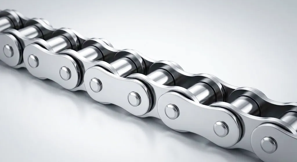
Catenary sag is one of those engineering realities that experienced conveyor designers think about constantly, yet it rarely gets the structured treatment it deserves in technical literature aimed at working professionals. In the context of roller chain conveyor systems — whether you are running a heavy-duty aggregate conveyor in Sheffield, a food-grade processing line in Birmingham, or a palletising system in a logistics hub near Manchester — the way your chain hangs between its support points directly determines chain wear rate, sprocket engagement quality, drive power demand, and ultimately the productive life of the entire drivetrain. Get the sag wrong in either direction and you will pay for it, either in premature failure from excess slack, or in punishing tensile overload from chains pulled too tight.
Roller chain catenary sag, defined technically as the perpendicular deflection of a freely hanging chain span measured at its midpoint, is governed by classical catenary mathematics — but in practice, engineers need fast, reliable methods that translate into setup and maintenance procedures on the workshop floor. This article works through the physics, the calculation framework, material considerations, real-world control strategies, and the common failure modes that arise when sag is mismanaged. It also examines why the choice of chain itself — its pitch, its construction, its lubrication-retaining geometry — has as much influence on acceptable sag tolerances as the tensioning hardware you install.
What Catenary Sag Actually Means for a Roller Chain Drive
The Physics of the Hanging Span
When a roller chain runs between two sprockets on a horizontal or near-horizontal conveyor, the slack side — the return strand — is not perfectly taut. Under its own weight it follows a curve. That curve is a catenary, the same shape a suspension bridge cable takes under gravity. The chain’s linear weight (mass per unit length, expressed in kg/m) combined with the unsupported span length and the applied tension determines how deep that curve drops at its lowest point. A chain with a pitch of 38.1 mm and a linear weight of 8.5 kg/m will sag more steeply over a 3-metre unsupported span than an equivalent pitch chain built from lighter materials over the same distance, all other things being equal. Understanding this relationship is the starting point for every sag calculation a maintenance engineer will ever need to perform.
Why Sag Matters More Than Most Engineers Expect
Excessive sag on the slack side causes the chain to contact support rails or guides in an uncontrolled way, generating abrasive wear on the outer link plates and damaging the underside of carriers and attachments. More critically, it creates dynamic instability as the drive sprocket pulls the chain taut at intermittent intervals rather than smoothly, inducing shock loads across every pin-bushing joint. Conversely, over-tightened chain eliminates sag entirely but places both bearings and roller chain pins under continuous high radial load, accelerating fatigue cracking in the link plates and crushing the grease film inside the bushings. Striking the right balance — and then maintaining it as the chain elongates through normal wear — is the practical engineering challenge this guide addresses.
Standard Sag Targets Across Industry
The widely accepted benchmark for horizontal roller chain conveyors, as published in BS ISO 606 and referenced in UK plant engineering practice, is to target a slack-side sag of approximately 2% of the centre-to-centre sprocket span. For a 2,000 mm centre distance, that translates to roughly 40 mm of midpoint deflection. However, this is a starting figure, not a universal law. Inclined conveyors, chains carrying heavy attachments, high-speed drives, and systems operating in environments where vibration amplification is a concern all require tighter tolerances — often 1.5% or even 1% of span length. Conversely, very slow, heavily loaded horizontal conveyors can tolerate slightly more sag without adverse consequences, provided adequate return-strand support is in place.
How to Calculate Roller Chain Catenary Sag — Step by Step
The simplified catenary sag formula used in engineering practice derives from the parabolic approximation of the full catenary equation — an approximation that remains accurate to within 1% for sag depths below 10% of span length, which covers virtually all practical conveyor designs. The governing expression is:
Where f is the midpoint sag in metres, w is the chain’s linear weight in newtons per metre (N/m), 엘 is the unsupported span length in metres, and 티 is the chain tension at the midpoint of the slack strand, measured in newtons. This is the form most commonly applied by UK conveyor designers working from chain manufacturer data sheets. To convert chain linear mass (kg/m) to linear weight (N/m), simply multiply by 9.81.
A horizontal aggregate conveyor operating in a quarry near Leeds uses a 38.1 mm pitch roller chain with a linear mass of 6.8 kg/m. The unsupported return-strand span is 2.4 m. The slack-side tension, measured by a strand tension gauge after commissioning, is 420 N.
w = 6.8 × 9.81 = 66.7 N/m
L² = 2.4² = 5.76 m²
8 × T = 8 × 420 = 3360 N
f = (66.7 × 5.76) / 3360 = 0.114 m = 114 mm
The 2% target for a 2,400 mm span is 48 mm. At 114 mm, this chain is running with significantly excessive sag and needs retensioning — a common finding on older UK quarry and aggregate plant conveyors where periodic tension checks have slipped from the maintenance schedule.
Factors That Shift the Sag Equation in Real Systems
Temperature
Carbon steel roller chains elongate under heat at roughly 11 micrometres per metre per degree Celsius. A 10 m conveyor chain running at 80°C in a Birmingham automotive paint-bake oven versus 20°C ambient will be about 6.6 mm longer — enough to drop sag by a measurable margin if no automatic tensioner is fitted. Stainless-grade alloys elongate at a slightly different rate and must be factored separately.
Wear Elongation
As pin-bushing interfaces wear, each link gains fractional length. ISO 606 specifies maximum permissible elongation at 3% for standard drive chains and often 1.5–2% for conveyor chains carrying attachments. A chain that has elongated 2% over a 3 m span adds roughly 60 mm to that span, directly increasing sag unless the take-up device has equivalent adjustment range. Monitoring elongation with a chain wear indicator tool should be a quarterly routine in any UK plant running continuous duty roller chain conveyors.
Inclination Angle
Once a conveyor exceeds about 15 degrees of incline, the component of chain weight acting perpendicular to the chain centreline (which drives sag) decreases — but the tight-side tension climbs steeply. The net effect is that inclined conveyors generally run with less sag on the return strand, but are more prone to over-tension faults if the take-up device is not properly calibrated. Steep incline conveyors operating in UK colliery remnant sites and deep-cut quarries frequently present both conditions simultaneously and require dedicated take-up calculations.
Attachment Loading
Many industrial conveyor chains carry attachments — flights, scrapers, brackets, buckets. These add point loads at regular intervals along the chain, distorting the clean catenary curve into a series of shorter catenary segments between attachment points. Calculating sag accurately requires treating each segment independently using the segment span and the local tension at each attachment location. Ignoring this in favour of a whole-span calculation typically underestimates midpoint sag by 15–25% in heavily loaded bucket elevator chains.
Roller Chain Material and Construction — Why It Defines Sag Behaviour
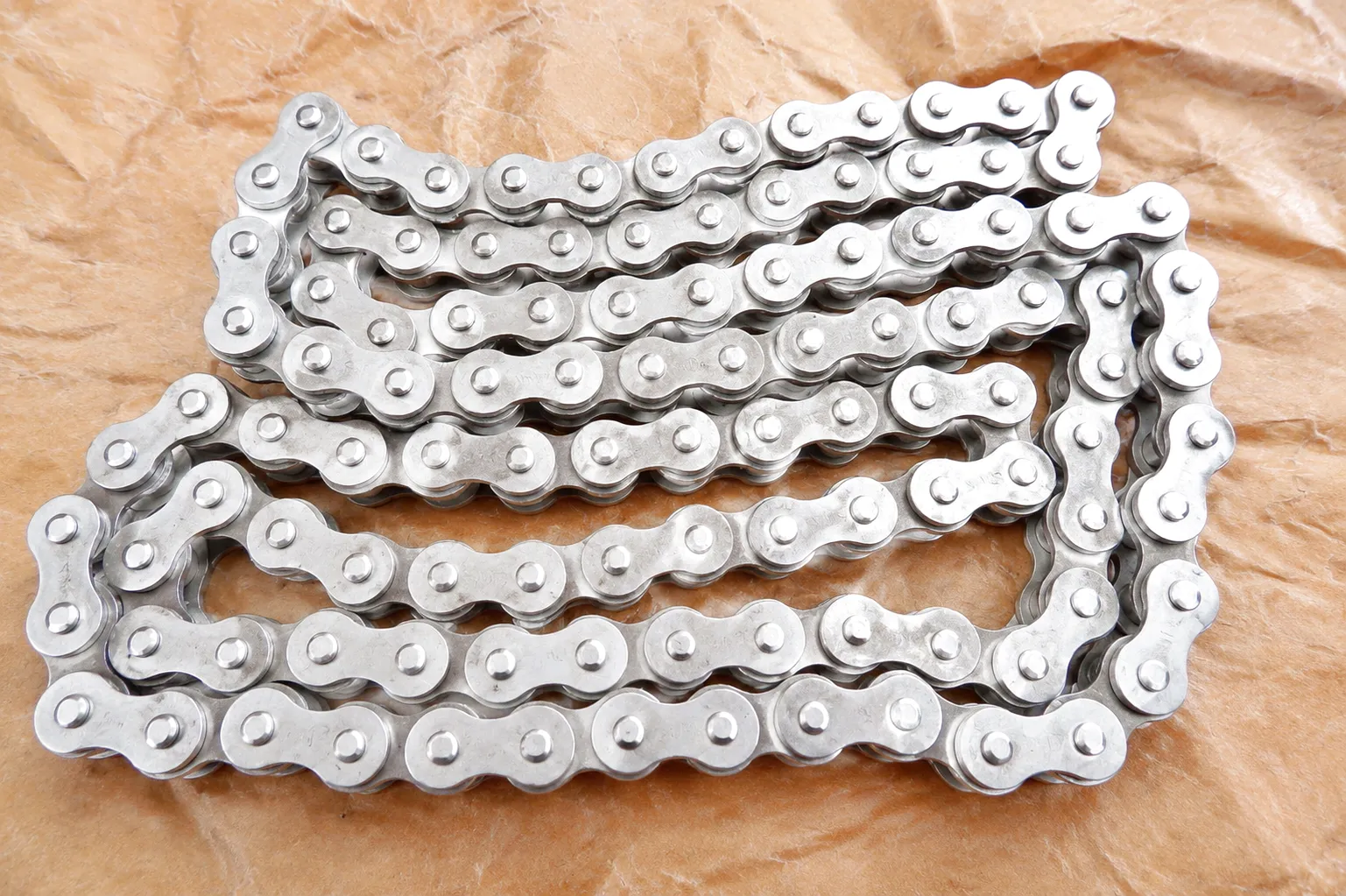
The physical properties of a roller chain’s constituent materials — specifically their density, elastic modulus, and surface hardness — directly govern both the linear weight term and the tension-bearing capacity that appear in the sag formula. This is not an abstract concern: two chains with identical pitch numbers can exhibit dramatically different sag behaviour depending on whether they are manufactured from standard carbon steel, case-hardened alloy steel, or a nickel-plated corrosion-resistant grade.
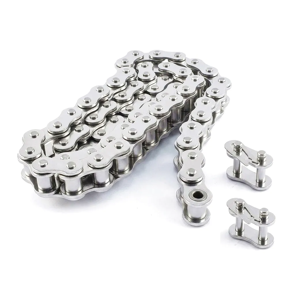
Standard carbon steel roller chains — typically manufactured from SAE 1045 to 1060 medium-carbon grades for link plates and SAE 4140 alloy steel for pins — strike a reasonable balance between linear weight (and therefore sag tendency) and tension capacity. Case-hardened link plates in the HRC 58–62 range significantly extend wear life without substantially increasing mass. Stainless steel variants, widely specified in UK food processing and pharmaceutical conveyor applications, carry about 5–8% more mass per unit length than comparable carbon grades, meaning their sag at equivalent tension will be proportionally greater — a calculation offset that designers often overlook during the transition from carbon to stainless specification.
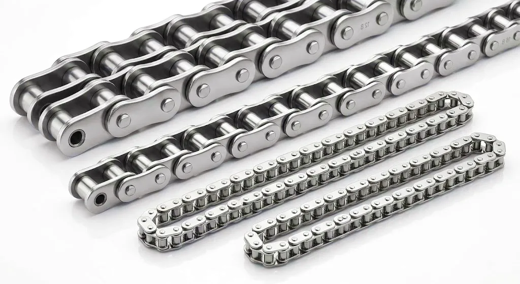
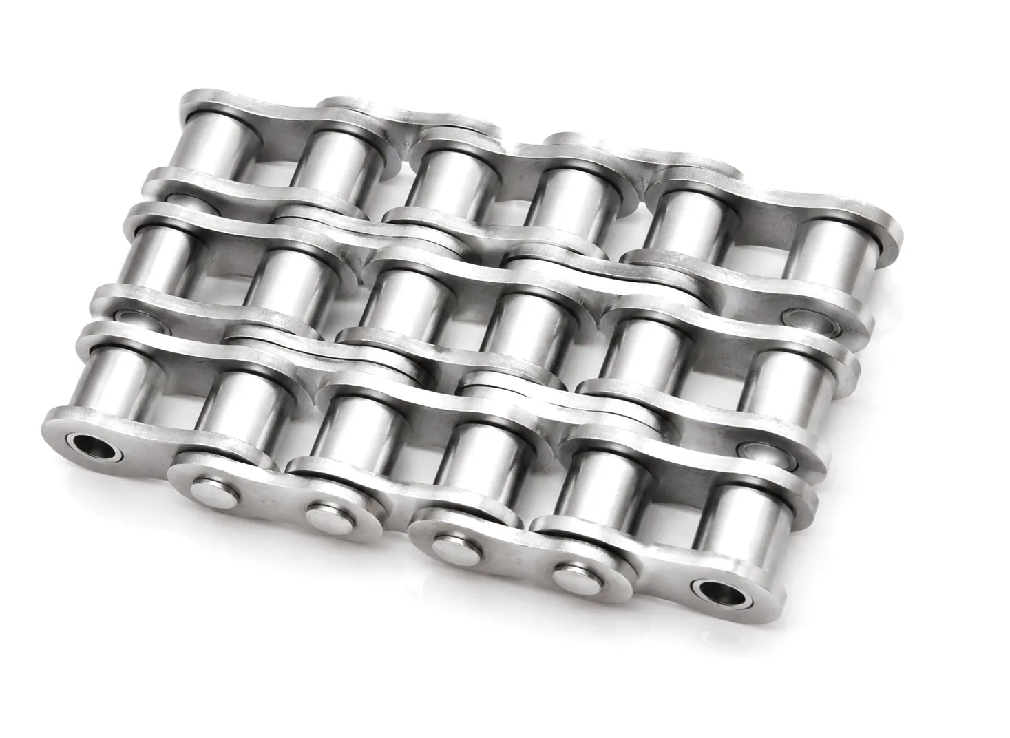
Hollow-pin and extended-pitch conveyor chains deserve particular mention. Extended-pitch designs, with pitches of 38.1 mm (ISO 12B-1 × 2) or 50.8 mm (ISO 16B-1 × 2) and beyond, increase the length of each unsupported segment between rollers, making them inherently more susceptible to micro-catenary effects between individual pins. When these chains carry a heavy attachment mass distributed unevenly along the strand, the local sag variation between attachment points can contribute to noise, vibration, and irregular sprocket tooth engagement. Selecting the correct extended-pitch chain for a given conveyor geometry is therefore inseparable from controlling sag.
Denser chain = more sag at equal tension. Always recalculate sag when switching chain grade or material — do not assume existing tensioner settings remain valid.
Roller Chain Technical and Performance Parameters
| 매개변수 | Typical Range / Value | Standard Reference | Notes |
|---|---|---|---|
| 피치 범위 | 6.35 mm – 101.6 mm | ISO 606 / BS 228 | Smaller pitch = less sag per unit length |
| Linear Weight (w) | 0.8 – 45 kg/m | Manufacturer Data Sheet | Multiply by 9.81 for N/m in sag formula |
| Link Plate Material | Carbon steel, Alloy steel, SS 304/316 | ISO 1083 / ASTM A29 | Stainless adds ~6% mass versus carbon |
| Pin Hardness | HRC 58 – 64 | ISO 606 | Critical for wear elongation control |
| Minimum Breaking Load | 3.5 kN – 850 kN | ISO 606 | Safety factor ≥ 7:1 for standard conveyors |
| Target Sag (Horizontal) | 1.5% – 2.5% of centre span | ISO 606 / OEM Guidelines | Tighten tolerance for high-speed or inclined |
| Max Permissible Elongation | 1.5% – 3.0% | ISO 606 | Replace at limit; sag increases proportionally |
| Thermal Expansion Coefficient | ~11 µm/(m·°C) (carbon steel) | ASTM E289 | Relevant in heated oven / outdoor UK environments |
| Operating Temperature Range | -30°C to +400°C (grade-dependent) | Manufacturer Specification | High-temp grades reduce elongation under heat |
| Roller Diameter Tolerance | ±0.03 mm (precision grade) | ISO 606 Class A | Tight tolerance reduces dynamic sag variation |
Practical Sag Control Methods for Industrial Conveyor Applications
Knowing the target sag and calculating the current sag are only two thirds of the challenge. The third element — keeping the roller chain within tolerance throughout its service life — demands the right combination of take-up hardware, support geometry, and maintenance discipline. The following methods are established in UK conveyor engineering practice and address the full range of duty cycles from light-duty packaging lines in Nottingham to the punishing 24/7 mineral processing conveyors found in South Wales and the North East.
Industrial Application Scenarios Where Sag Control Is Critical
Steel and Metals Processing — Sheffield and Rotherham
Heavy-section roller chain conveyors transferring steel billets, coils, and tube sections in Sheffield’s remaining steelworks and Rotherham’s rolling mills operate in environments where thermal gradients across the conveyor run can exceed 50°C between the furnace-exit zone and the ambient inspection station. This makes thermally induced sag variation a constant management challenge. Chains specified for these duties are typically large-pitch, high-capacity grades — pitches of 50.8 mm to 101.6 mm are common — and take-up devices must accommodate the combined effect of thermal elongation and wear elongation across chains that can be 20–30 metres in total length.
Automotive Manufacturing — Coventry and Birmingham
Overhead conveyor systems in automotive body-in-white and paint shop lines in Coventry and Birmingham demand sub-millimetre repeatability in chain positioning. Excessive sag in an overhead conveyor causes body panels to arrive at welding or painting stations at inconsistent heights, creating rejections that are extremely costly in high-volume production. These applications typically use precision-grade roller chains with tight pitch tolerances, combined with spring-loaded or pneumatically actuated take-up systems that can respond to rapid thermal changes during oven cycling. The roller chain here functions as a precision positioning device, not merely a power transmission element.
Food and Beverage Processing — Yorkshire and East Midlands
Food-grade conveyor applications in Yorkshire’s extensive confectionery and dairy processing sectors demand that roller chains are not only dimensionally controlled but also constructed from materials that resist corrosion and can be cleaned with high-pressure wash-down equipment. Stainless steel chains running on HDPE slider rails are the dominant specification. The higher linear mass of stainless roller chains means that the nominal 2% sag target often needs to be tightened to 1.5% to prevent the slack strand from contacting drip trays or hygiene guards — an issue that food safety inspectors flag under Food Standards Agency guidelines. Drainage geometry of the return strand is also considered during sag optimisation, as pooling of wash water in a sagging return can create bacterial harbouring sites.
Aggregate and Quarrying — Wales, Yorkshire, and Scotland
Aggregate conveyors face perhaps the harshest sag management environment of any UK industry. Abrasive stone dust infiltrates every joint and bushing, rapidly increasing wear elongation rates. Wet weather — a constant condition across Welsh quarries and Scottish hillside operations — reduces chain lubrication effectiveness and adds water weight to the chain itself, temporarily increasing the effective linear weight used in sag calculations. Roller chains in quarry service typically need elongation checks every four to six weeks rather than quarterly, and take-up devices must have generous adjustment travel — a minimum of 5% of total chain length — to remain useful through a complete service cycle. Heavy-duty X-ring sealed chains or nickel-plated variants that resist water-induced corrosion are increasingly specified for outdoor quarry conveyors throughout the UK.
Failure Modes Linked to Incorrect Sag Management
The engineering literature on roller chain failure tends to focus on fatigue, corrosion, and lubrication breakdown as primary failure drivers. These are all valid and important, but in the field — particularly among UK maintenance engineers responding to conveyor stoppages — sag-related failures consistently represent a significant proportion of unplanned downtime events. Recognising these failure signatures early is what separates reactive maintenance from condition-based practice.
Chain Jump-Off Under Load Surge
When a heavily sagging roller chain encounters a sudden load surge — a jammed product, an uneven feed of heavy stone, an emergency start from rest — the energy stored in the sag causes the chain to slap upward and disengage from the drive sprocket teeth. This is a sudden and potentially dangerous failure, as the chain can whip under released tension. It is among the most common sag-related failure modes reported in UK quarrying and recycling plant service records.
Accelerated Side-Plate Wear from Guide Contact
Excessive sag on the return strand of a conveyor running through a narrow frame often causes the chain to rub repeatedly against side guides or support channel flanges. This generates a distinctive wear pattern on the outer link plate edges — a bright, polished stripe along the plate side that appears well before the pin-bushing interfaces show significant wear. It is an early-warning indicator observable during routine visual inspections, and correcting sag when this mark appears prevents premature chain replacement.
Sprocket Tooth Skipping and Irregular Pitch Engagement
As a roller chain elongates through wear, the effective pitch of the chain increases relative to the fixed pitch of the sprocket. When combined with insufficient take-up, the elongated, sagging chain begins to ride outward on the sprocket tooth flanks rather than seating correctly in the root. This causes the characteristic “skipping” sensation felt through the conveyor frame and heard as a rhythmic clunking noise, which ultimately leads to accelerated sprocket tooth wear and potential tooth fracture if not corrected promptly.
Bearing Overload from Excessive Over-Tensioning
Attempting to “solve” sag by simply running the chain extremely tight is a common error, particularly among maintenance teams working without engineering support. Over-tensioned roller chains place radial loads on head shaft and tail shaft bearings that can exceed the bearing’s rated dynamic load capacity. UK plant maintenance records show bearing failures typically occurring within three to six months of extreme over-tensioning, creating failures far more expensive than the original sag problem would have caused through a properly managed tensioning adjustment.
Ever Power — Precision Roller Chain Manufacturing for Global B2B
Ever Power operates a precision manufacturing facility producing roller chains that are engineered to maintain tight sag control throughout their service life — not just at commissioning. The key to this performance lies in the dimensional discipline applied during manufacturing: pin diameter tolerances held to ±0.01 mm, link plate thickness consistency within ±0.02 mm, and roller outer diameters controlled to ISO 606 Class A across every production batch. These tolerances directly translate to predictable linear weight values and consistent elongation behaviour, the two variables that sag calculations depend on most critically.
Ever Power’s customisation capabilities extend well beyond standard pitch and strand configuration. Engineering teams can specify chains with extended pitch for large-span conveyors, modified attachment link plates for specific carrier geometries, hollow-pin designs for lubrication distribution systems, and material selections spanning carbon steel, alloy steel, stainless steel grades 304 and 316, and nickel-plated variants for outdoor or corrosive environments common in UK coastal and chemical processing sites. Every custom specification is supported by full material traceability documentation — an important requirement for UK customers operating under ISO 9001 certified quality management systems.
The Ever Power supply chain is structured to support both large-volume frame agreements and rapid-response emergency replacement orders — a critical distinction for UK plant operators who cannot afford extended conveyor downtime. Technical sales support is available to review your conveyor specifications and recommend the correct chain grade, pitch, and take-up system configuration for your sag control requirements.
Customer Success Story — Sheffield Steel Handling Plant
A structural steel section producer operating a multi-strand roller chain cooling bed conveyor at its Sheffield facility approached Ever Power after experiencing three unplanned shutdowns within a single quarter. The cooling bed conveyor — responsible for transferring hot-rolled angle sections from the rolling mill exit to the bundling station — was equipped with 50.8 mm pitch carbon steel chains across a 22-metre centre distance. The maintenance team had been managing elongation by periodic screw take-up adjustment, but the take-up travel on the original equipment was inadequate, running out of adjustment range well before chains reached the 3% elongation limit specified for replacement.
The result was sag exceeding 380 mm on the slack strand — more than four times the 2% target of 110 mm for a 5.5-metre unsupported intermediate span. Under the thermal cycling of the cooling bed operation, where chain temperatures varied between 40°C at start-up and 120°C under full load, the sag variation was enough to cause repeated chain jump-off from the drive sprocket cluster at the mill exit end, triggering both production losses and a health and safety incident report.
Ever Power’s technical team conducted an on-site engineering survey, during which sag was measured under operating conditions using a laser reference line. The solution combined three elements: replacement of all strands with Ever Power’s precision-grade 50.8 mm pitch alloy steel chain, installation of a gravity take-up device with 280 mm of vertical travel (replacing the screw take-up), and addition of intermediate support rails at 1,800 mm centres to bring each unsupported span within a safe catenary sag range of 54 mm at nominal operating tension. Post-installation monitoring over eight months recorded zero unplanned shutdowns related to sag, and chain elongation rates in the first service cycle ran 18% lower than the previous chain — attributable to the tighter pin and bushing tolerances in the Ever Power product.
고객 리뷰
“The dimensional consistency of the Ever Power chains made a visible difference from the first installation. Our elongation rate is down significantly and the gravity take-up solution they recommended has removed the weekly tensioning routine from our maintenance schedule entirely.”
“We specified a stainless variant for our wash-down conveyor and Ever Power’s technical support was thorough — they flagged that the higher linear weight of stainless would require a tighter sag target and helped us recalculate before we committed to the tensioner specification. That kind of upstream support saves real money.”
“Competitive price and fast delivery — the emergency stock programme meant we had replacement chains on site within 48 hours after an unexpected failure at our quarry operation. For a product that has to be exactly right dimensionally, the consistency across batches has been impressive.”
자주 묻는 질문
Real questions from plant engineers, maintenance managers, and procurement teams across the UK.
Ready to Solve Your Roller Chain Sag Challenge?
Talk to Ever Power’s engineering team. Custom chains, precise tolerances, UK-ready logistics.