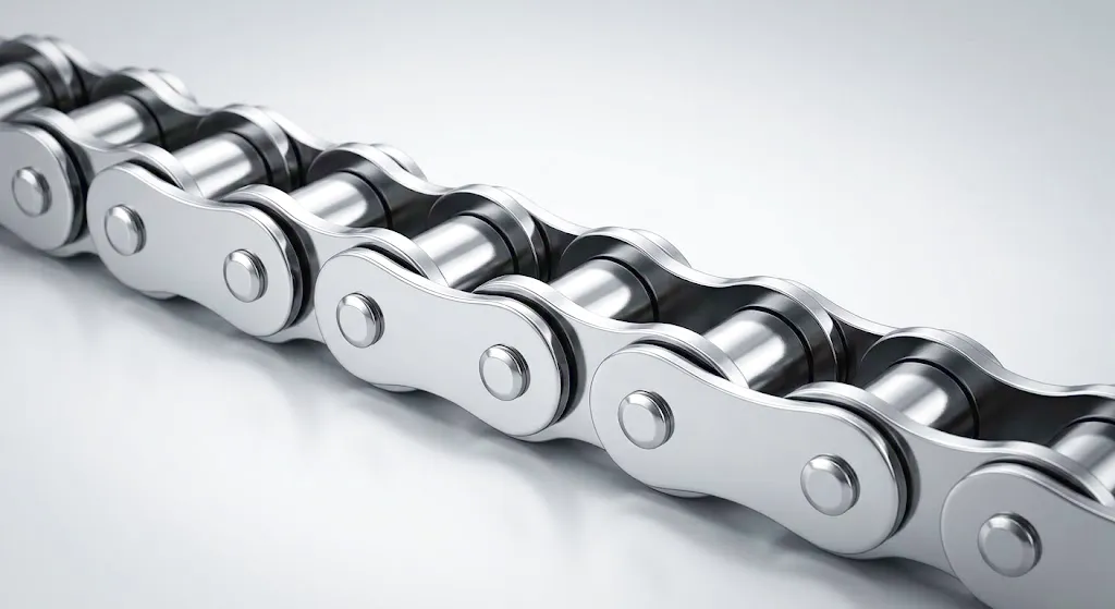
Why Getting Roller Chain Length Right Matters
When a conveyor line stalls mid-shift at a food processing plant in Birmingham, or a drive system skips teeth on a packaging rig in Sheffield, the root cause is often something deceptively simple: an incorrectly sized roller chain. Getting the chain length wrong — even by a single pitch — creates misalignment, excess tension, premature sprocket wear, and ultimately, unplanned downtime that costs far more than the chain itself. Across the UK’s manufacturing belt, from the West Midlands to Yorkshire, engineers are relearning that accurate roller chain length calculation is not a secondary concern but a foundational discipline. Whether you are specifying a new conveyor system, replacing a worn loop on a legacy agricultural machine, or commissioning a custom industrial drive for a new facility in Leeds or Manchester, understanding how to calculate roller chain length with precision is the difference between a system that runs quietly for years and one that fails within months. This guide walks you through the engineering principles, the mathematics, real-world application scenarios, and the technical parameters that define a properly specified roller chain drive.
The Fundamental Calculation Formula for Roller Chain Length
Every roller chain length calculation begins with the same foundation: the chain must wrap around two or more sprockets and span the centre distance between them without slack or excessive tension. The industry-standard formula used by mechanical engineers across the UK and internationally expresses chain length in terms of the number of chain links (pitches) rather than millimetres or inches, because chain is manufactured and sold in discrete link counts. The formula is:
This formula is derived from geometrical principles that account for the straight spans of chain running between sprockets and the wrapped arc on each sprocket. Breaking it down into its three components makes the physics intuitive. The first term, 2C/p, captures the two straight-run spans of chain that exist between the sprockets on the tight side and the slack side of the drive. The second term, (N + n)/2, accounts for the total number of pitches consumed by wrapping around both sprockets — essentially a simplified average of the two sprocket circumferences. The third term is a correction factor that adjusts for the angular difference between the sprockets. When both sprockets are identical in size (N = n), this correction term becomes zero, as expected. When a significant size difference exists, as is common in speed-reduction drives used in coal handling facilities in South Yorkshire or heavy steel processing in the Black Country, this correction term becomes meaningful and must not be omitted.
Because the result L is almost never a whole number, engineers round up to the nearest even integer. Using an even number of links is strongly preferred in standard roller chain practice because it avoids the need for an offset link (also called a crank link), which introduces a weak point in the chain and reduces the overall rated tensile strength by approximately 20%. Once the link count is established, multiply by the pitch to convert back into a physical chain length in millimetres or inches.
Step-by-Step Roller Chain Length Calculation: A Worked Example
Gather the Drive Geometry Parameters
Before you can calculate roller chain length, you must establish four fixed values: the chain pitch, the number of teeth on each sprocket, and the centre-to-centre distance between the sprocket shafts. Consider a practical UK example drawn from a conveyor system in a distribution centre in Coventry: the drive specifies a 12B-1 chain with a pitch of 19.05mm. The drive sprocket has 19 teeth (n = 19) and the driven sprocket has 38 teeth (N = 38). The shaft centre distance is 500mm. With these parameters confirmed, the calculation can proceed. It is worth emphasising that centre distance is frequently the parameter most prone to measurement error on site — always verify using a calibrated distance gauge rather than a tape measure, particularly where vibration or previous wear may have shifted bearing housings even by a few millimetres.
Compute the Centre Distance in Pitches
Convert the centre distance into pitch units by dividing by the chain pitch: C/p = 500 / 19.05 = 26.25 pitches. This dimensionless ratio is what drives the first term of the formula. The first term of the roller chain length formula becomes 2 × 26.25 = 52.5 pitches. This single term alone tells you that if both sprockets were the same size and had zero wrap correction needed, the chain would be approximately 52.5 pitches long — just covering the two straight spans. The conversion into pitches early in the calculation prevents compounding of unit-conversion errors that can occur when engineers mix millimetre and inch values, a common issue when specifying replacement chains for older UK machinery originally designed to Imperial measurements.
Apply the Sprocket Wrap Term
The second term is (N + n) / 2 = (38 + 19) / 2 = 28.5 pitches. This represents the combined arc length of chain that wraps around both sprockets simultaneously — the sections that are in contact with the sprocket teeth at any given moment. At a 1:2 speed ratio, this is a significant proportion of total chain engagement. Engineers specifying roller chain drives for agricultural machinery in the East Midlands — combine harvesters, baling equipment — often underestimate this term when dealing with large driven sprockets, leading to undersized chain orders that cause operational delays during harvest windows. Always check the full arithmetic before ordering.
Calculate the Correction Factor
The third term, the correction factor, is: ((N – n) / (2 × pi))^2 × (p / C). Substituting: ((38 – 19) / (2 × 3.1416))^2 × (19.05 / 500) = (19 / 6.2832)^2 × 0.0381 = (3.024)^2 × 0.0381 = 9.145 × 0.0381 = 0.35 pitches. This is a non-trivial correction at this sprocket ratio, and at larger ratio differences — such as 1:4 or 1:5 speed reduction drives common in heavy industrial conveyors in South Wales steelworks or automotive pressing facilities in the West Midlands — the correction term can reach 1.5 to 2.5 pitches, sufficient to take chain count from an even number to an odd one, requiring a different design decision.
Sum and Round to Even Links
Adding all three terms: L = 52.5 + 28.5 + 0.35 = 81.35 pitches. Rounding up to the nearest even integer gives L = 82 links. The physical chain length is then 82 × 19.05mm = 1,562.1mm, or approximately 1,562mm. This is the specified length to order. If centre distance is adjustable, the drive should be assembled with the chain at 82 links and the centre distance shortened slightly to remove slack, then tensioned via an adjustable mounting or tensioner sprocket. Many roller chain drive systems in UK light manufacturing facilities — packaging lines, bottling plants, automotive sub-assembly — are designed with deliberately adjustable mounting plates to accommodate the natural elongation of roller chain over its service life, typically 2–3% over the first 5,000 hours of operation.
Choosing the Right Roller Chain for Your Drive Application
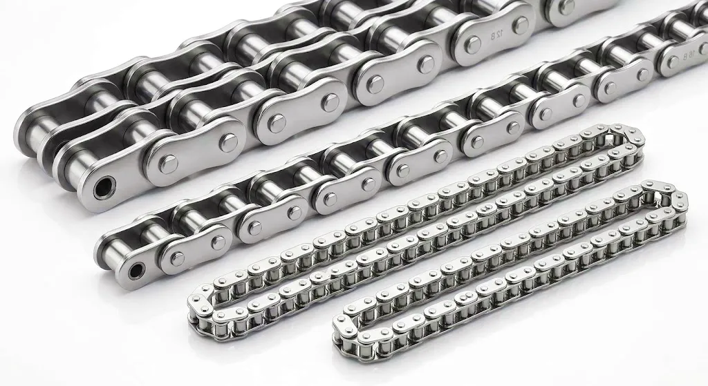
Calculating chain length is only one half of the specification process. You must simultaneously confirm that the chain series — its pitch, breaking load, and plate thickness — is appropriate for the torque and speed being transmitted. Heavy-duty applications in UK quarrying, mineral processing in North Wales, or bulk materials handling in Humberside require roller chain with higher tensile ratings than standard conveyor duty. Two purpose-built high-performance roller chains that deserve particular attention for demanding drive applications are:
How Roller Chain Works: Principle and Core Materials
Operating Principle
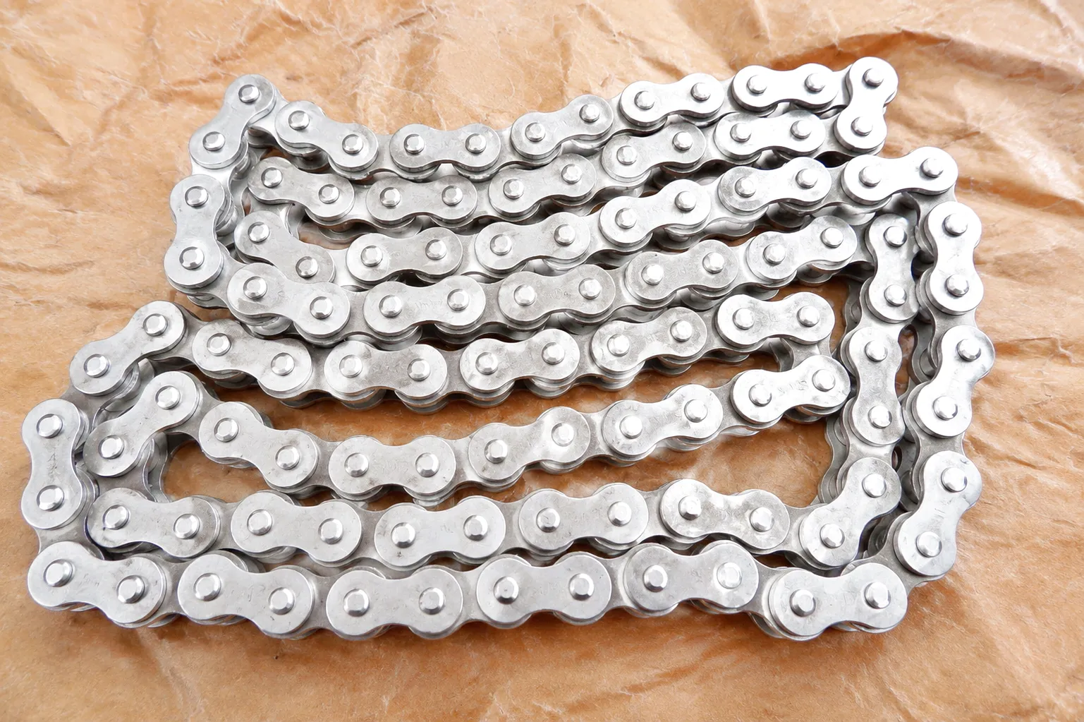
A roller chain transmits power through a series of articulated links, each consisting of inner and outer plate pairs connected by pins, bushings, and rollers. As the drive sprocket rotates, its teeth engage the rollers seated within the chain’s inner links. The rollers spin freely on the bushing, reducing sliding friction at the point of tooth engagement to a controlled rolling contact. This rolling engagement is the defining advantage of roller chain over flat belt or V-belt drives in high-load, low-speed applications. The chain then wraps around the driven sprocket, where it imparts torque through the same rolling tooth contact before departing on the slack side. The tight-side tension minus the slack-side tension equals the effective pull that transmits useful power through the system. On a UK food production line running around the clock in Grimsby, or a beverage canning plant near Wakefield, this continuous articulation of thousands of link cycles per hour demands lubrication at every pin-bushing interface to manage wear and thermal stress.
Роликті тізбек өндірісіндегі негізгі материалдар
The performance and longevity of a roller chain are inseparable from its material composition. High-quality roller chain manufactured for demanding UK industrial applications typically uses case-hardened or through-hardened carbon steel (such as AISI 1045 or AISI 52100 bearing-grade steel) for the pins and rollers, where hardness values of HRC 55–62 are standard. The inner and outer link plates are manufactured from high-carbon or alloy steel and stamped to precise dimensional tolerances before heat treatment. The bushings — the cylindrical sleeves that sit between the pin and the roller — are typically sintered powder-metal components with oil-impregnated porosity, which provides initial lubrication and extends the service interval. For corrosive environments, such as coastal processing facilities in Hull or offshore support workshops in Aberdeen, stainless steel grades 304 and 316 are used throughout, sacrificing some tensile strength for dramatically improved resistance to salt air, cleaning chemicals, and moisture. Nickel-plated chain options are specified for moderate corrosion resistance at lower cost, while self-lubricating chains featuring PTFE-impregnated bushings are selected where external lubrication is impractical or prohibited, such as in food-grade conveyor systems under strict hygiene regulations.
Roller Chain Technical Performance Parameters Table
| Chain Standard / Series | Қадам (мм) | Breaking Load (kN) | Максималды жылдамдық (м/с) | Pin Material | Plate Material | Әдеттегі қолданылуы |
|---|---|---|---|---|---|---|
| BS/ISO 06B-1 | 9.525 | 8.9 | Up to 8 | Case-hardened steel | Carbon steel (BS EN 10083) | Light conveyor, small agricultural |
| BS/ISO 08B-1 | 12.7 | 17.8 | Up to 7 | Through-hardened alloy | Medium carbon steel | General manufacturing, packaging |
| BS/ISO 12B-1 | 19.05 | 28.9 | Up to 5.6 | Alloy steel HRC 58–62 | High-carbon steel | Industrial conveyor, distribution |
| BS/ISO 16B-1 | 25.4 | 60.0 | Up to 4.5 | Alloy steel, induction hardened | High-tensile alloy plate | Heavy engineering, quarrying |
| ANSI 80 (ASA No.80) | 25.4 | 57.8 | Up to 5 | Case-hardened chromium alloy | Carbon / alloy steel | OEM equipment, North American spec plant |
| 120HSP (Caterpillar) | 38.1 | 170+ (enhanced) | Low-speed / high-torque | Premium bearing-grade alloy | H-plate high-fatigue alloy steel | Caterpillar earthmoving, mining OEM |
| 316 Stainless Series | 12.7 – 38.1 | 12–80 (grade dependent) | Up to 4 | 316 stainless steel | 316 stainless steel | Food, coastal, offshore, chemical |
Core Technical Advantages of Modern Roller Chain
Industrial Application Scenarios Across the UK
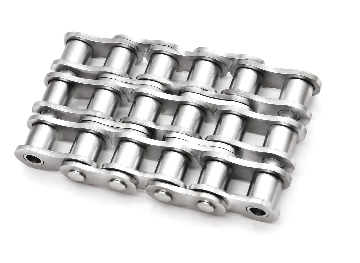
Agricultural Machinery Drives — East Midlands & Yorkshire Farms
Combine harvesters, potato harvesters, round balers, and grain augers in the arable farmland of Lincolnshire and North Yorkshire rely heavily on roller chain drives for threshing mechanisms, straw walkers, and header drives. These environments expose chain to abrasive crop debris, moisture, and variable loading, demanding roller chain with sealed joints and adequate lubrication intervals. Roller chain length calculation for seasonal agricultural equipment must account for sprocket wear that accumulates during intensive harvest periods, often requiring annual replacement of both chain and sprockets as matched sets to avoid accelerated wear on new chain running against worn tooth profiles.
Automotive Assembly Conveyors — Birmingham & West Midlands
The West Midlands automotive supply chain — encompassing component manufacturers in Coventry, Solihull, and surrounding towns — uses roller chain extensively for overhead conveyors, floor-level power-and-free systems, and body assembly lines. These applications demand precise roller chain length calculation because conveyor loops often span hundreds of metres within large assembly halls. Accumulated pitch error across thousands of links can create drive irregularity, noise, and ultimately chain jumping. High-precision roller chain manufactured to tighter-than-standard pitch tolerances — sometimes ±0.05mm per link versus the standard ±0.1mm — is specified for automotive production environments where smooth, synchronised transfer is essential for JIT manufacturing schedules.
Steel and Metal Processing — Sheffield & South Yorkshire
Sheffield’s long-established metal processing and specialist steel manufacturing heritage creates demand for heavy-duty roller chain in rolling mill table drives, forging press transfer mechanisms, and bar processing conveyors. These applications involve extreme loads, elevated temperatures from hot-processed steel billets, and scale debris that is highly abrasive. Roller chain selected for Sheffield metalworking environments typically specifies large-pitch heavy series chain (BS 24B, 32B, or 40B) manufactured from high-tensile alloy steel with special surface coatings to resist scale adhesion. Calculating the correct chain length in these applications also requires accounting for thermal expansion of both the chain and the supporting steelwork at operating temperature, a factor that changes effective centre distance and therefore affects tension.
Mining & Quarrying Equipment — Wales & Northern England
Welsh slate quarries, limestone workings in the Pennines, and open-cast coal sites in Northumberland use roller chain in conveyor drives, coal cutter haulage systems, and crusher-feed apron feeders. These environments impose the most severe operating conditions on chain: near-continuous operation under high load, contamination with abrasive minerals, and the ever-present risk of shock loading when oversized lumps enter a crushing system. For these applications, chain service life is directly determined by how accurately the drive geometry — including roller chain length and tension — has been specified during commissioning. An under-tensioned chain in a heavy haulage drive will whip under load, generating bending fatigue cracks in the link plates that are the precursor to sudden chain fracture.
Optimum Centre Distance and Chain Sag Guidelines
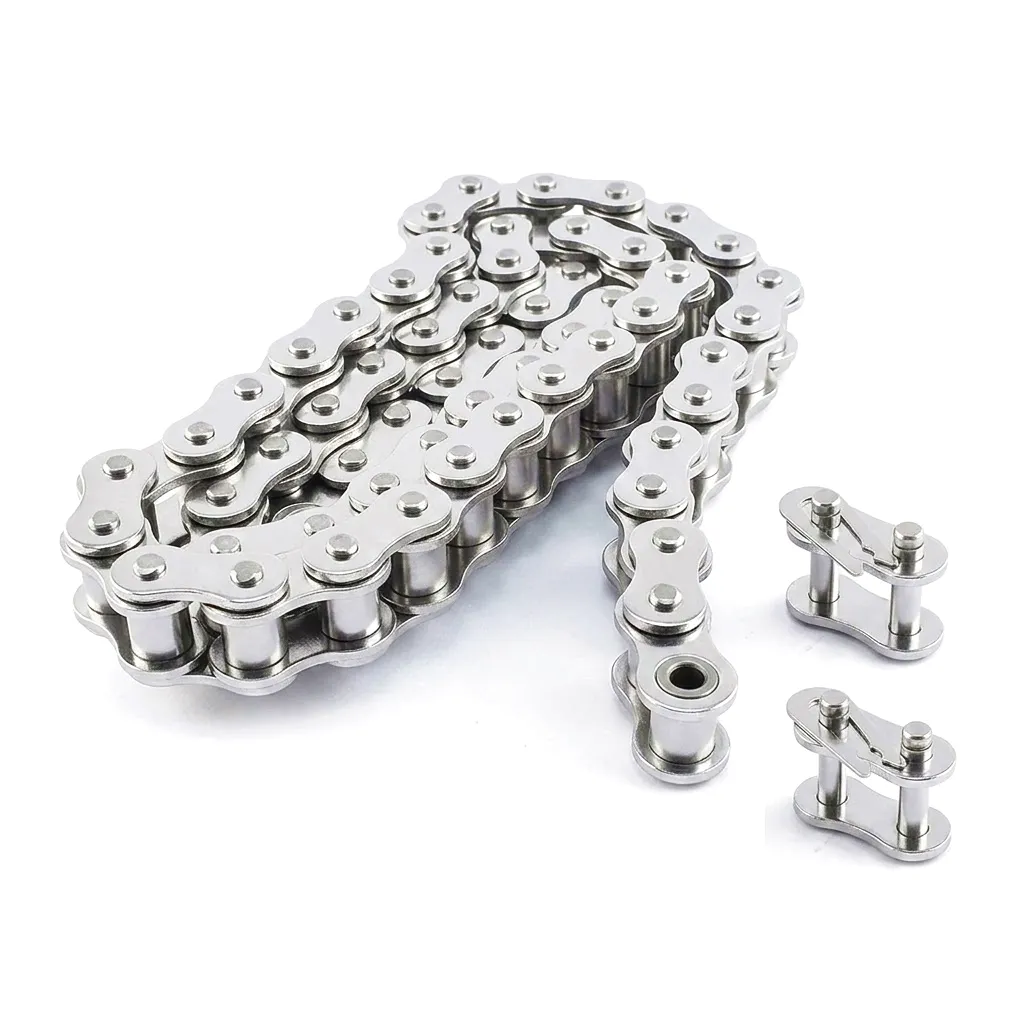
The centre distance between drive and driven shafts has a direct relationship with roller chain length that goes beyond simple arithmetic. There are engineering guidelines that define the optimal centre distance range for any given pitch and sprocket sizes, and operating outside these boundaries — whether too close or too far — creates specific problems. The ideal centre distance for most roller chain drives is 30 to 50 times the chain pitch. For a 19.05mm pitch 12B-1 chain, this means preferred centre distances ranging from approximately 572mm to 952mm. Below 30 pitches, the small wrap angle on the smaller sprocket reduces the number of teeth in engagement, increasing the load per tooth and accelerating sprocket wear. Excessively short centre distances also exacerbate the polygon effect — the rhythmic speed variation inherent to chain drives — making the drive noisier and more prone to vibration-induced fatigue. At the opposite extreme, very long centre distances increase chain sag on the slack side. A general rule maintained by UK drive engineering standards recommends that the permitted slack, measured as a vertical sag at the midpoint of the slack span, should not exceed 2% of the span length. For a 1,000mm slack span this means no more than 20mm of sag. Exceeding this value causes the chain to undulate at speed, creating whipping forces and shock loads each time the slack span enters the driven sprocket. Tensioner sprockets or adjustable take-up units are the standard solution in these situations and must be included in the drive geometry when calculating the overall roller chain length for a three-sprocket arrangement.
Ever Power Roller Chain: Precision, Customisation & Supply Chain Strength
Ever Power operates a fully integrated roller chain manufacturing facility with over two decades of specialisation in precision chain products for global B2B customers. Our manufacturing capability extends from standard ISO and ANSI series stock chains through to fully engineered custom roller chain assemblies built to customer drawings, application briefs, or sample-match specifications. For UK engineering buyers — whether procurement managers at a Sheffield fabrication house, maintenance engineers at a Birmingham automotive plant, or agricultural equipment distributors serving the East Anglian market — Ever Power provides the combination of consistent quality, rapid turnaround, and comprehensive technical support that distinguishes a genuine manufacturing partner from a simple catalogue supplier.
Our customisation capabilities cover every critical roller chain parameter. We manufacture in pitches from 6.35mm to 76.2mm across single, double, triple, and quad-strand configurations. Custom attachment plates — straight, bent, extended, or drilled to customer pattern — are stamped and assembled in-house. Special materials including marine-grade 316 stainless, duplex stainless, and carbon-fibre reinforced polymer options are available for specialist applications. For OEM customers in the UK construction equipment sector — plant dealers in Bristol, Glasgow, and Belfast — Ever Power provides brand-specified performance chains including Caterpillar-compatible HSP series chains engineered to match or exceed OEM breaking loads and fatigue ratings. Our ISO 9001 certified quality management system governs every stage of production from raw material inspection through finished chain verification, with full dimensional and mechanical test certification available on request.
Customer Success Story: Leeds Bulk Handling Facility
A bulk aggregates processing and distribution facility on the outskirts of Leeds had been experiencing premature roller chain failure on three of its primary inclined conveyor drives. The conveyors transported crushed limestone from ground-level hoppers to an elevated screening deck, operating 22 hours per day across six days a week. Chains were failing at approximately four to five months of service, well below the target twelve-month replacement cycle, and each unplanned stoppage cost the facility an estimated £4,200 in lost throughput and emergency maintenance labour.
The site maintenance team contacted Ever Power’s technical sales engineers and requested a full drive audit. Our engineers visited the Leeds facility and identified two concurrent problems. The first was a roller chain length specification error: chains had been ordered at the correct nominal length, but no correction for thermal expansion of the supporting steelwork had been applied. The facility’s conveyor support structure — spanning approximately 14 metres — expanded during summer operating conditions by approximately 8mm, effectively reducing the chain tension to near-zero at operating temperature and causing the slack-side chain to oscillate and wear asymmetrically against the guide rails. The second problem was a material specification mismatch: the original chain was standard carbon steel, which in combination with the moist limestone dust environment was experiencing significant bushing corrosion between lubrication cycles.
Ever Power redesigned the specification: chains were upgraded to nickel-plated 16B-2 double-strand with sealed joints, and a spring-loaded take-up unit was added to each drive to maintain tension across the thermal operating range. The revised roller chain length was calculated using the corrected centre distance at mean operating temperature, adding 4mm to the effective centre distance in the formula. Chains were supplied with full dimensional certification to BS EN ISO 1275. Since installation, the Leeds facility has completed 14 continuous months of operation without an unplanned chain-related stoppage, and the annual cost of chain maintenance at that site has reduced by approximately 62%.
What UK Customers Say About Ever Power Roller Chain
“We had been through three suppliers in two years trying to solve our conveyor chain issue at our Sheffield pressing plant. Ever Power’s team actually understood what we needed, specified the right chain length with thermal allowance built in, and delivered on a three-week lead time. The nickel-plated 16B-1 chains have been running without issue for nearly eighteen months. Genuinely impressive.”
“Ever Power supplied us with custom extended-pitch roller chain for our bulk potato elevator at our Lincolnshire processing site. The custom attachment plates were exactly to our drawing, tolerance was within spec, and the documentation pack for our quality records was complete on delivery. Their technical team helped us recalculate the optimum chain length for our new elevator height, which saved us from having to use an offset link. We won’t go elsewhere.”
“As a plant hire company operating Caterpillar excavators and dozers across sites in the North West, keeping track chain in good condition is a constant operational challenge. Ever Power’s 120HSP and C100HSP roller chains match the OEM spec closely, hold up well in the mud and grit we work in, and arrive with proper certification. The pricing is competitive with the OEM alternative, and the technical team helped us set up a stock-holding plan so we are not waiting weeks for replacements.”
Frequently Asked Questions About Roller Chain Length & Specification
Voice-search friendly answers for UK industrial buyers and maintenance engineers
Ready to Specify the Right Roller Chain for Your Drive?
Talk to Ever Power’s engineering team. We provide free drive calculations, custom specification support, and competitive pricing for UK B2B buyers.