Breaking Load vs Working Load:
Understanding Roller Chain Strength Ratings
Every power transmission system depends on chains that perform reliably under real-world stress. Yet misreading a chain’s strength rating remains one of the costliest mistakes in British manufacturing and industrial operations today.
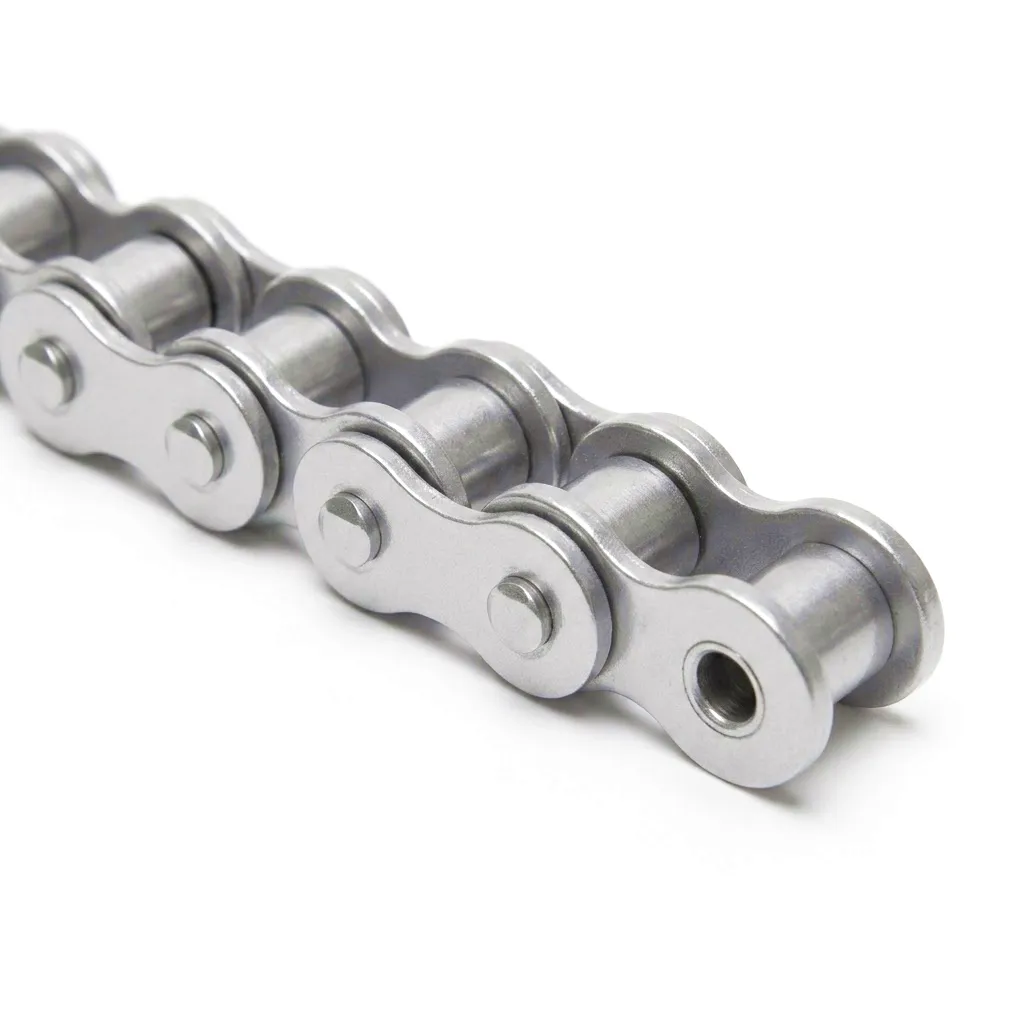 When procurement engineers at West Midlands fabrication plants or logistics hubs near Birmingham begin specifying roller chain for a new conveyor system, one question cuts through almost every technical discussion: how much load can this chain actually take? The answer is rarely a single number. A roller chain carries two fundamentally different strength ratings — its breaking load and its working load — and the gap between these figures is not a safety footnote. It is the engineering boundary between reliable operation and catastrophic failure.
What Breaking Load Actually Measures in Roller Chain Engineering
Breaking Load Defined
The breaking load (also called minimum tensile strength or MTS) is the measured force at which a roller chain permanently fails under a controlled static tensile test. This figure is determined by clamping both ends of the chain in a testing rig and applying a steadily increasing tensile force until the chain fractures. The result is recorded in kilonewtons (kN) or occasionally in tonnes-force, and it forms the ceiling of a chain’s structural capacity. Crucially, this number tells you absolutely nothing about how much load the chain should carry during normal service — it simply defines the point of destruction. Standards bodies including BS EN ISO 606 specify minimum breaking load values for each chain pitch and configuration, and reputable manufacturers such as Ever Power provide certified test documentation alongside every batch shipment to UK customers.
The Testing Method
Breaking load tests are always conducted under static conditions, which means the chain is pulled slowly and the load is applied without vibration, shock, or directional change. In industrial reality, chains rarely see purely static loads. The chain on a press machine in a Sheffield metalworking factory experiences dynamic jolts every cycle. A conveyor chain in a Birmingham automotive plant encounters start-stop loading, vibration from adjacent machinery, and occasional shock loads from a sudden jam. None of these real-world conditions are replicated in the breaking load test, and that is precisely why breaking load alone cannot be used to size a chain for real applications.
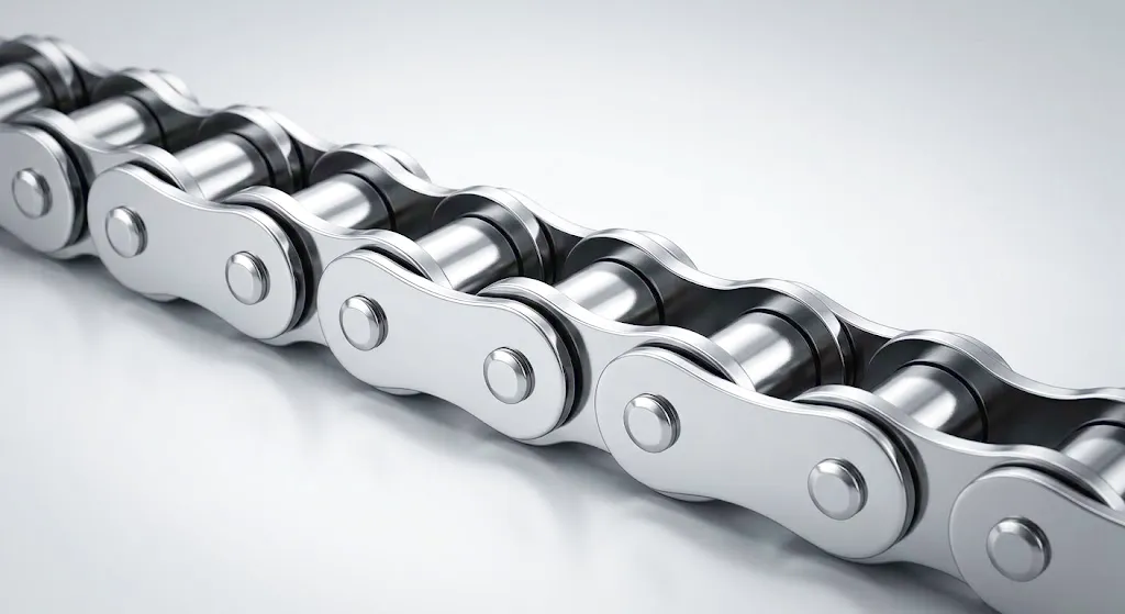
A roller chain’s breaking load is ultimately a metallurgical statement. It reflects the quality of the steel alloy selected for side plates and pins, the precision of the hardening and heat treatment processes, and the integrity of the assembly. High-grade roller chains manufactured to BS EN ISO 606 standards use carbon-manganese or alloy steel with carefully controlled case hardening on the rollers and pins, and through-hardening on side plates to optimise tensile strength and fatigue resistance simultaneously. These material choices directly determine where the breaking load figure lands, and they are the invisible foundation beneath every data sheet entry.
Working Load: The Number That Governs Real-World Drive System Design
If breaking load is the absolute structural limit, working load (sometimes called safe working load or SWL) is the maximum tension a roller chain should sustain during continuous operation without accelerating wear or risking fatigue failure. This is the figure that drive system designers, mechanical engineers, and plant maintenance managers across the UK should prioritise when sizing a chain for any application. Working load accounts for the real dynamics of service — including shock loading, vibration, fatigue cycling, and the inevitable degradation of lubrication over time.
Service Factor Application
Working load is derived from breaking load by applying a service factor — typically ranging from 7:1 to 13:1 for roller chains in industrial applications. A standard BS 08B-1 chain with a minimum breaking load of 17.8 kN would therefore carry a working load recommendation of roughly 1.4 to 2.5 kN under normal smooth drive conditions. For shock-loaded applications common in Yorkshire mining-support equipment or Scottish paper mills, the service factor increases further to preserve fatigue life.
Fatigue vs Static Failure
Most roller chain failures in service are not caused by a single overload exceeding the breaking load. They result from repeated cyclic loading that progressively weakens the side plates, pins, and bushings through fatigue crack propagation. A chain running consistently at 80% of its working load in a well-lubricated, well-aligned system will outlast a chain running at 50% working load on a poorly aligned sprocket with dried-out lubricant. The working load figure is only meaningful in the context of the full operating environment.
Dynamic Loading Correction
British Standard drive design guides recommend applying correction factors for the drive type, speed, and duty cycle before comparing the calculated effective tension against the chain’s working load. A chain driving a rotary kiln at a Lancashire cement plant must account for gravitational loading on the return strand, thermal expansion effects on centre distance, and the inertia of a large rotating mass during start-up — none of which appear in a static tensile test result.
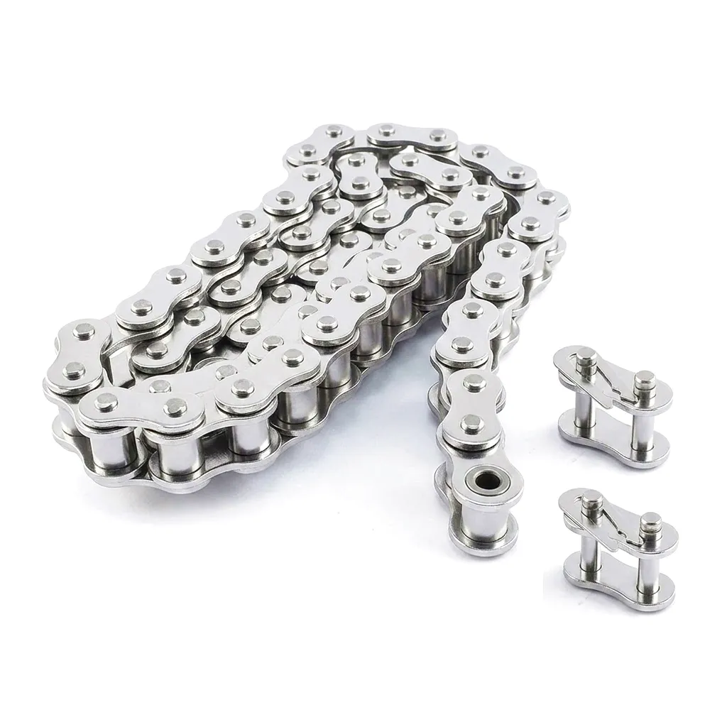 A clear illustration of why working load matters more than breaking load in daily operations: a precision roller chain threading through a high-speed conveyor system at an automotive assembly facility outside Birmingham must sustain millions of stress cycles during its service life. At no point should the effective tension in that drive approach anywhere near the breaking load — the working load boundary is what keeps the system in the safe, predictable zone where planned maintenance replaces unplanned downtime.
The Safety Factor: Engineering Margin Between Rated Strength and Operational Reality
The ratio between breaking load and working load is the safety factor, and understanding how engineers determine this ratio is essential for responsible chain selection. In the UK, the Mechanical Engineers’ Society recommendations and BS EN ISO 606 both provide guidance on appropriate safety factors, but these figures are starting points, not fixed rules. The true safety factor for any specific application must be calculated by the design engineer based on five categories of variable that can each independently elevate operational loads well beyond the simple static tension figure.
Temperature Effects
Operating temperatures above 150°C in foundry environments reduce steel tensile strength noticeably. Safety factors must be increased proportionally for chains in high-heat applications such as kiln drives or furnace conveyors.
Shock and Vibration
Shock loads — from jammed material on a conveyor or a sudden stop on a press drive — can instantaneously multiply effective chain tension by a factor of 3 or more. Drive systems in Sheffield forging workshops or heavy fabrication plants typically require safety factors of 10:1 or higher.
Misalignment Penalty
Lateral misalignment between drive and driven sprockets introduces a transverse force component that raises tension in the side plates well beyond the calculated drive force. A common cause of premature chain failure in UK food processing plants where sprocket positions shift during washdown cycles.
Lubrication State
Inadequate lubrication increases pin-bushing friction dramatically. This friction loss manifests as an elevated effective tension that the chain must overcome — effectively increasing the load demand without any change in the external payload. Well-maintained lubrication regimes can extend chain service life by three to five times compared to poorly lubricated equivalents.
Roller Chain Technical Performance Parameters — BS EN ISO 606 Reference Data
The following table presents key strength rating data for common European-standard roller chain sizes. Working load figures assume a service factor of 8:1 under smooth, well-lubricated drive conditions. For applications involving shock loading, elevated temperatures, or corrosive environments, additional safety margin should be applied and specialist technical advice sought before finalising chain selection.
| Chain Size (BS/ISO) | Pitch (mm) | Breaking Load (kN) Min. | Working Load (kN) @ 8:1 | Berat (kg/m3) | Diameter Pin (mm) | Side Plate Material | Diameter Penggelek (mm) |
|---|---|---|---|---|---|---|---|
| 08B-1 | 12.70 | 17.8 | 2.2 | 0.69 | 4.45 | Keluli Karbon | 8.51 |
| 10B-1 | 15.875 | 22.2 | 2.8 | 0.93 | 5.08 | Keluli Karbon | 10.16 |
| 12B-1 | 19.050 | 28.9 | 3.6 | 1.15 | 5.72 | Keluli Aloi | 12.07 |
| 16B-1 | 25.400 | 60.0 | 7.5 | 2.71 | 8.28 | Keluli Aloi | 17.02 |
| 20B-1 | 31.750 | 95.0 | 11.9 | 3.84 | 9.54 | Keluli Aloi | 19.56 |
| 24B-1 | 38.100 | 160.0 | 20.0 | 7.00 | 14.63 | Keluli Aloi | 25.40 |
| 32B-1 | 50.800 | 250.0 | 31.3 | 10.55 | 17.81 | High-Grade Alloy | 30.99 |
Data based on BS EN ISO 606 simplex chain standards. Breaking load = minimum tensile strength. Working load @ 8:1 service factor for smooth, well-aligned drives.
The Material Science That Determines Roller Chain Strength: Steel Grades, Heat Treatment and Manufacturing Precision
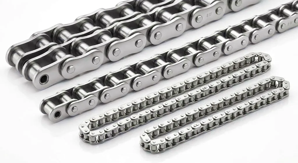
The interplay between material selection and manufacturing precision ultimately determines whether a chain achieves — or exceeds — its certified breaking load. Ever Power’s production process incorporates multi-stage quality verification at each sub-assembly stage, with dimensional checks that go beyond standard BS EN ISO 606 compliance to deliver chains where breaking load figures consistently exceed the minimum by a meaningful margin, providing UK buyers with genuine engineering confidence.
Industrial Application Scenarios Where Correct Strength Rating Selection is Critical
Automotive Assembly Line Conveyors — West Midlands and Sunderland Plants
Roller chains operating on body-shop overhead conveyors or floor-level drag chains in UK automotive facilities carry both the weight of vehicle bodies and the dynamic forces of acceleration and braking during controlled line movement. These systems operate continuously across three shifts, which means the chain must sustain its working load for tens of millions of loading cycles annually. Engineers specify chains with breaking loads typically six to eight times the calculated maximum effective tension, with duplex or triplex configurations selected when the single-strand working load would need to exceed 60% of the rated value for that pitch. The Rantai Penggelek Atas Getah 20B-G1 is widely used in such environments, where the rubber top surface prevents damage to painted vehicle bodies while the underlying chain structure delivers the working load capacity required by heavily loaded conveyor tracks.
Steel Handling and Rolling Mill Drives — Sheffield and Scunthorpe Operations
The steel industry in Sheffield and Scunthorpe represents one of the most demanding roller chain environments in British manufacturing. Drive chains in rolling mill sections face combined shock loading from the biting action of rolls engaging bar stock, high ambient temperatures from process heat radiation, and exposure to cooling water and scale particles that accelerate wear. For these drives, the safety factor calculation must include a shock factor of 2.0 to 3.0, a temperature correction for service above 150°C, and a contamination factor that accounts for abrasive wear on the pin-bushing interface. The result is typically a working load selection at less than 8% of the breaking load, demanding high-capacity heavy-duty roller chains with hardened alloy steel construction throughout.
Agricultural Machinery Drives — Yorkshire and East Anglian Arable Operations
Combine harvesters, round balers, and grain handling elevators used across Yorkshire’s arable farming regions demand roller chains that maintain their strength ratings under highly variable loading — from near-zero tension during light crop conditions to sudden high-load peaks when cutting dense standing cereal crops in late summer harvests. The seasonal duty cycle also introduces a fatigue life consideration that differs from continuous industrial service: chains may accumulate concentrated loading during a 6-week harvest period, then sit idle, then return to service with no opportunity for inspection or relubrication. Agricultural chain specifications therefore use conservative working load limits, with chains selected at 15 to 20% of breaking load to provide the additional safety margin needed for unmanned field operation where breakdown means immediate and costly harvest delay.
Packaging Line Drives and Case Handling — Milton Keynes and Bristol Distribution Centres
High-throughput packaging and distribution facilities in the logistics corridor between Milton Keynes and Bristol run roller chain drives on carton erectors, case sealers, palletisers, and sortation conveyors around the clock. The working load demands in these applications are generally moderate relative to breaking load, but the duty cycle is extreme — chains operate at speeds of 1.5 to 3 m/s continuously for up to 20 hours per day. At these duty levels, fatigue life rather than absolute working load typically governs chain selection. The Rantai Penggelek Atas Getah 24B-G1 is an excellent fit for package-contact conveyor lines in these facilities, where the rubber pad surface provides positive grip on cardboard cases while the 38.1 mm pitch chain construction maintains adequate working load capacity for multi-lane palletising conveyor systems.
Ever Power: Precision Roller Chain Manufacturing with Full Customisation Capability
Ever Power has built its position in the global roller chain supply market on a straightforward commitment: certified breaking load values that reflect actual material performance, not minimum acceptable test results. Every chain leaving the Ever Power manufacturing facility undergoes multi-stage quality verification — from incoming raw material inspection through completed assembly tensile testing on a calibrated test rig — ensuring that the breaking load and working load figures provided to customers represent genuine, repeatable performance, not marketing claims.
The Ever Power customisation capability extends well beyond the standard pitch and material combinations listed in BS EN ISO 606. UK customers can specify non-standard attachment types, extended pin lengths for multi-strand assemblies, modified plate geometry for integration into OEM machinery, and alternative surface treatments including zinc-nickel plating, corrosion-resistant coatings, or specialty polymer coatings for chemical or food-grade environments. Each customisation is engineered with the same rigour applied to standard products — including full recalculation and documentation of the resulting breaking load and working load ratings under the modified specification.
Certified Breaking Load Testing
Every production batch is tensile-tested on calibrated equipment. Test certificates with actual measured breaking loads accompany every shipment on request.
Custom Working Load Engineering
For non-standard duty cycles or challenging environments, Ever Power engineers work with your team to establish validated working load parameters before manufacture begins.
Kebolehpercayaan Rantaian Bekalan UK
Stock held at UK distribution partners with express despatch options ensures that planned maintenance shutdowns and emergency replacements across British manufacturing plants receive the right chain, documented and ready to fit, within the planned maintenance window.
OEM Design Integration
Ever Power works directly with OEM machinery builders — from agricultural equipment manufacturers in Lincolnshire to conveyor system integrators in the Midlands — to specify and validate roller chain components during the machine design phase rather than as an afterthought.
Customer Success Story: Sheffield Heavy Fabrication Plant Eliminates Unplanned Downtime Through Correct Strength Rating Application
A mid-sized structural steel fabricator based near the Tinsley viaduct in Sheffield had been experiencing repeated roller chain failures on the main transfer conveyor serving their plasma cutting hall. The conveyor moved steel plate sections — weighing up to 2.8 tonnes per section — from the incoming material store to the cutting beds. The drive had been specified using 24B-1 simplex chain based solely on pitch compatibility with the existing sprockets, with no documented calculation of the effective tension or safety factor.
Failures were occurring every 8 to 12 weeks, consistently at the point of maximum curvature around the drive sprocket. Post-failure examination showed classic fatigue fracture characteristics in the side plates — entirely consistent with a chain operating significantly above its working load rather than having exceeded its breaking load in a single event. The effective tension calculation, conducted as part of the Ever Power technical consultation, revealed that the chain was sustaining peak tensions of approximately 38 kN under start-up conditions — a figure that placed the effective load at nearly 24% of the 24B-1 breaking load under what should have been a smooth, well-aligned drive. The compounding factor was a 6-degree misalignment between the drive and driven sprockets that had developed gradually as the conveyor frame settled, adding a transverse stress component to the side plates on every revolution.
The remediation involved re-specifying to 32B-1 duplex chain with a documented working load margin of 7:1 under worst-case dynamic conditions, combined with sprocket realignment and the introduction of automatic lubrication. Over the 14 months following the remediation, the conveyor ran without a single unplanned chain failure — a result that saved the plant an estimated 120 hours of unplanned downtime and over £90,000 in production loss, tooling damage, and emergency call-out fees from the previous annual failure pattern.
Key Outcome Metrics
Ulasan Pelanggan
“The Ever Power technical team didn’t just send us a catalogue — they actually worked through our effective tension calculation with us and flagged that our original chain selection was undersized for the shock loading on our press feed. Their 32B-1 chain has been running without issue for over a year now. The breaking load documentation they provided was detailed enough to satisfy our insurance engineer’s query straightaway.”
James T., Plant Engineering Manager — Sheffield, South Yorkshire
“We had been buying chain based on pitch alone for years. Ever Power changed our approach completely — they explained working load ratings in terms our maintenance team could actually apply, and the custom 20B-1 chain they supplied for our food-grade conveyor in Grimsby came with full material certification and a test report. The working load margin on that chain is better than anything we’d sourced locally at comparable cost.”
Sarah M., Maintenance Director — Food Processing Facility, Lincolnshire
“For our OEM agricultural machinery line in Lincolnshire, we needed a chain supplier who could deliver custom attachment modifications without compromising the published working load data. Ever Power did exactly that — they recalculated and re-documented the working load for our modified 16B-1 attachment chain, which was critical for our own machinery CE marking process. Lead times and shipping to our facility have been consistently reliable over two years of orders.”
David R., Chief Design Engineer — Agricultural Machinery OEM, Lincolnshire
Soalan Lazim
How do I calculate the correct working load for a roller chain drive system in a UK industrial application?+
To calculate the working load correctly, you need to determine the maximum effective tension in the drive using the formula: effective tension (N) = transmitted power (W) / chain speed (m/s). Then multiply by your service factor — typically 7 to 13 depending on shock level, duty hours, and lubrication type. The result must be less than the chain’s published working load for that pitch and construction. For UK drives involving shock-loaded machines, BS EN ISO 606 guidance recommends service factors of 10:1 or higher. Ever Power engineers can assist with this calculation for your specific duty — email [email protected] with your power, speed, and drive geometry data.
What is the difference between breaking load and tensile strength when I am comparing roller chain datasheets from different UK suppliers?+
Breaking load and minimum tensile strength (MTS) refer to the same property — the tensile force at which the chain fractures in a static test. Some UK suppliers use “tensile strength” while others use “breaking load”; both should quote the same figure when conforming to BS EN ISO 606. The key comparison point is whether the figure quoted is a minimum guaranteed value or an average measured value. Minimum values (as required by BS EN ISO 606) are the safe basis for design; average values are higher and should not be used as design limits.
Which roller chain size and breaking load rating would you recommend for a heavy conveyor drive running in a Sheffield steel fabrication facility with known shock loading?+
For a steel fabrication conveyor handling heavy plate stock in Sheffield, we typically recommend starting from 24B-1 or 32B-1 chain depending on your drive sprocket speed and transmitted power. Given the known shock loading characteristic of steel handling drives, apply a service factor of 10:1 minimum. This means your calculated maximum effective tension should not exceed 10% of the breaking load. For most heavy fabrication conveyors in Sheffield, 32B-1 duplex chain with a combined breaking load of 500 kN offers the working load margin needed for reliable continuous service. Contact Ever Power at [email protected] for a duty-specific recommendation with full calculation documentation.
How much does a custom-rated roller chain with certified breaking load documentation cost compared to a standard BS chain from UK stockholders?+
The price premium for certified breaking load documentation — including batch test certificates with actual measured breaking loads — is typically 5 to 12% above a standard catalogued chain price depending on pitch and quantity. For custom configurations (modified plate geometry, non-standard attachments, or specialty surface treatments), pricing depends on volume and lead time. Ever Power provides competitive pricing for UK customers, particularly on repeat orders and OEM supply agreements. Request a detailed quote at [email protected] with your specification and expected annual volume to receive accurate pricing.
Where can I find a reliable roller chain supplier in the UK who can confirm whether my existing chain working load rating is correctly specified for my Birmingham automotive plant conveyor?+
Ever Power provides technical review services for existing roller chain installations, available to UK customers including automotive facilities in the Birmingham and West Midlands region. Submit your current chain specification, drive arrangement data, and any failure history to [email protected] and our engineering team will review the working load adequacy against your actual drive parameters. This service is provided without obligation as part of Ever Power’s commitment to correct chain application in UK industry.
When should I upgrade from a simplex roller chain to a duplex or triplex configuration to increase my working load capacity without changing the drive sprocket pitch?+
Moving from simplex to duplex configuration roughly doubles the available working load for the same pitch, while keeping the same sprocket tooth profile and centre distance geometry. This is typically the correct approach when your calculated effective tension under the service factor exceeds the simplex working load but the drive design prohibits increasing the chain pitch — common in retrofitting scenarios on older machinery in UK manufacturing plants where the sprocket shafts are already at a fixed position. Triplex further increases capacity, though bearing loads on the shaft become the limiting factor at that stage. Ever Power can supply duplex and triplex versions of all standard BS EN ISO 606 chains on competitive lead times for UK delivery.
© Ever Power Industrial Chain Division · UK B2B Enquiries Welcome · BS EN ISO 606 Certified
suntingan oleh gzl