How to Perform a Roller Chain Drive Safety Factor Calculation
A practical engineering walkthrough for mechanical engineers, plant managers, and procurement specialists across UK industry — from Birmingham manufacturing floors to Sheffield’s steel processing plants.
📐 Safety Engineering
🏭 UK Manufacturing
Reach our technical sales team: [email protected]
What the Safety Factor Actually Means in Roller Chain Engineering
The safety factor (often written as Sf or n) in roller chain design is the ratio of the chain’s minimum tensile strength (also called breaking load) to the maximum allowable working load in the application. Expressed as a formula: Sf = Breaking Load / Maximum Working Tension. A result above 1.0 means the chain is theoretically safe; real engineering practice demands a far larger margin.
Manufacturing tolerances, fatigue accumulation, thermal expansion, and real-world shock loads all eat into that margin. Industry guidance — including ANSI/ASME B29.1 and BS ISO 10823 — recommends minimum safety factors ranging from 7 to 11 depending on the application type, operating environment, and whether shock loading is present. In heavy-duty UK industrial settings, values below 7 should prompt immediate re-engineering of the drive system.
It is critical to distinguish between static and dynamic safety factors. A static calculation uses peak tensile load under steady-state conditions. The dynamic safety factor accounts for cyclic loading, chain articulation at the sprocket, and the fatigue limit of the link plates and pins — which is considerably lower than the chain’s quoted breaking load. For most drive applications running continuously in UK plants, the dynamic approach is the correct one.
Working Principle and Core Material Science of Roller Chains
Step-by-Step: The Roller Chain Drive Safety Factor Calculation
The calculation framework below follows ISO 10823 methodology adapted for UK industrial practice.
Begin by establishing the actual design power the drive must transmit. This is not simply the rated motor output. You multiply the nominal transmitted power (P) by a service factor (Ks) that accounts for the nature of the load: smooth and uniform, moderate shock, or heavy shock. British Standards tables and major chain manufacturers’ engineering data categorise common UK applications — conveyors, agitators, compressors, crushers — by their typical Ks values. A smooth electric-motor-driven conveyor might carry Ks = 1.0, while a heavy reciprocating crusher driven via PTO in an aggregate quarry near Derby could carry Ks = 1.7 or higher. The formula is: Pd = P x Ks, with Pd expressed in kilowatts (kW).
With design power established, convert it to a chain tension force. The effective (or tangential) tension is calculated from: Ft = (Pd x 1000) / v, where v is the chain pitch velocity in metres per second (m/s). Chain pitch velocity is determined by: v = (p x z x n) / 60000, where p is the chain pitch in millimetres, z is the number of sprocket teeth, and n is the sprocket rotational speed in RPM. Getting this number right is fundamental — errors here cascade directly into an incorrect safety factor. Many drive failures in UK plants have been traced to velocity being estimated rather than measured directly under operating conditions.
At higher chain speeds, centrifugal force contributes additional tension that does not transmit power but does stress the chain. This centrifugal tension is: Fc = m x v², where m is the chain mass per unit length (kg/m) — found in manufacturer specification tables — and v is the chain velocity in m/s. At low speeds (under 3 m/s) this term is negligible; at speeds above 8 m/s it can become significant and must not be ignored. The total maximum chain tension used in the safety factor denominator is then: F_max = Ft + Fc. In high-speed applications such as roller chain drives on packaging machinery in Nottingham food plants, neglecting centrifugal tension is a common and expensive mistake.
Now compute the achieved safety factor: Sf = F_break / F_max, where F_break is the chain’s minimum tensile (breaking) strength in Newtons (N), obtained from the chain manufacturer’s certified specification sheet. Compare Sf against the minimum recommended value for your application category. If Sf meets or exceeds the recommended minimum, the selected chain is adequate. If it falls short, you must either select a higher-pitch or double-strand chain, reduce speed, or reduce load — each of which changes the denominator and brings Sf up to an acceptable value. Document this comparison in your design record as it forms part of your CE marking technical file under UK machinery regulations post-2021.
The breaking load figure on a chain datasheet represents a one-time static pull-to-failure value. In cyclic operation, the link plates and pins are exposed to fluctuating stress. The fatigue endurance limit of quality carbon-steel chain plates is typically 15–18% of the minimum tensile strength. For a true safety factor against fatigue failure — which is how the vast majority of roller chains actually fail in continuous industrial duty — you should compute: Sf_fatigue = F_endurance / F_max. This will produce a substantially lower number than the static Sf, and it is the figure that should be driving your chain selection in any application running more than 8 hours per day or subjected to cyclically varying loads, as commonly encountered in Birmingham’s automotive component manufacturing sector.
Lubrication method has a direct bearing on which safety factor is achievable in practice. ISO 10823 distinguishes between Type A (manual or drip lubrication), Type B (oil bath or slinger disc), and Type C (forced circulation). As speed increases beyond 2 m/s, moving from Type A to Type B or C lubrication substantially extends chain life and allows the published power ratings — and therefore the implied safety factors — to be fully utilised. Dry-running chains, which are sometimes encountered in the UK food sector where oil contamination must be avoided, require a conservative upward adjustment of the service factor Ks (typically add 0.5–1.0), which reduces the effective safety factor and may necessitate a chain upgrade or stainless-steel food-grade variant with appropriate certified breaking load data.
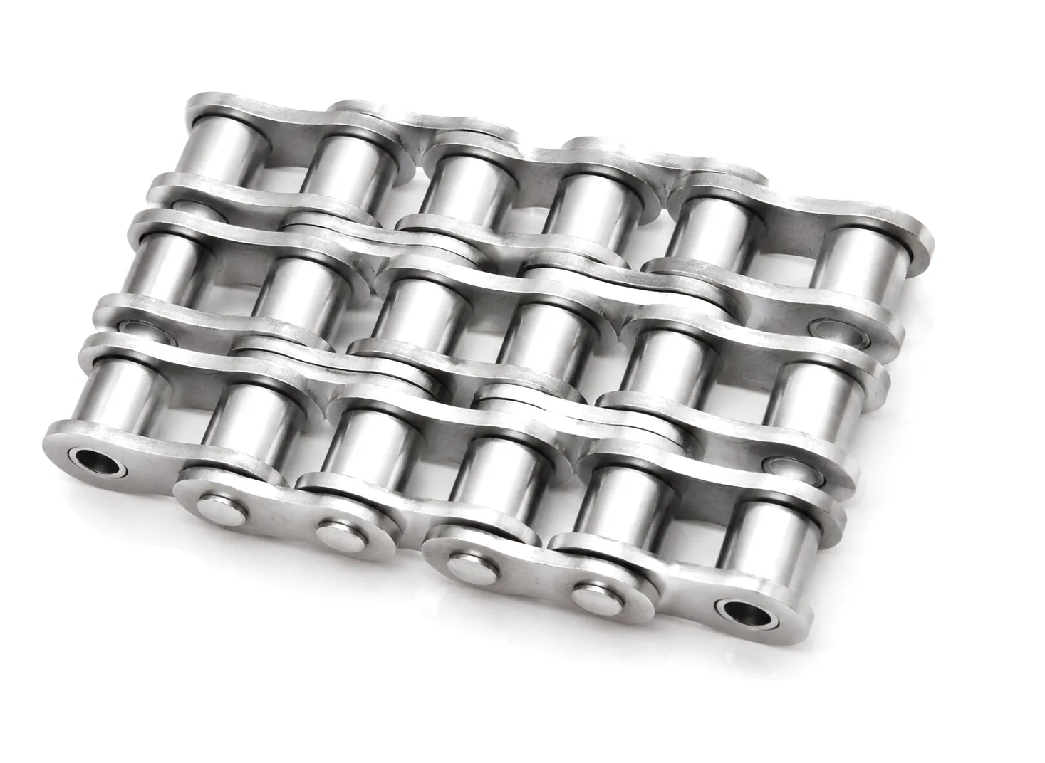
Roller Chain Technical Performance & Safety Parameter Table
Reference data for standard BS/ANSI roller chain grades. Always cross-check against certified manufacturer datasheet for the specific chain ordered.
Sf = Safety Factor. Values are indicative; verify with the full ISO 10823 selection table for your specific operating conditions.
Roller Chain Drive Safety Calculations Across UK Industrial Application Scenarios
Track-type excavators and crawler dozers operating around Sheffield’s infrastructure projects impose extreme shock loading on their drive chains — loads that can spike to three or four times the nominal calculated figure during rock cutting or stump removal. For these applications, the minimum recommended static safety factor is 12–15, and the chain specification should always call for a dedicated high-strength engineered grade. The Corrente de rolos de alta resistência 120HSP-00 para Caterpillar is purpose-designed for exactly these conditions, with a minimum breaking load substantially exceeding standard ANSI 120 catalogue values and shot-peened link plates to maximise fatigue resistance.
Sheffield’s steel industry, though considerably transformed from its Victorian peak, remains home to significant precision metals, specialty alloys, and cold-rolling operations. Roller chain drives in rolling mill auxiliary systems face moderate to heavy shock loads and are frequently exposed to elevated temperatures (50–80°C ambient near furnace areas) which degrade lubricant viscosity and can reduce chain tensile strength by up to 8% at sustained temperatures above 60°C. Safety factor calculations here must incorporate a thermal derating factor — typically 0.9 for 60°C operating environments — reducing the effective breaking load in the Sf numerator and requiring a proportionally heavier chain grade to maintain compliance with minimum recommended Sf values.
The West Midlands automotive supply chain depends heavily on precisely-calculated roller chain drives for transfer lines, press feeds, and robotic loading systems. These applications are characterised by high-cycle, medium-load duty — the very conditions where fatigue-based safety factor calculations are most critical. An Sf of 7–8 against breaking load often masks a fatigue Sf of only 4–5 once link plate endurance limits are applied. Birmingham-based plant engineers who have implemented fatigue-based chain selection routinely report 40–60% increases in replacement intervals, dramatically reducing production downtime in precision-margin environments where one unplanned stoppage can cascade through JIT supply agreements.
Food-grade conveying systems across Yorkshire’s extensive food manufacturing sector present a unique safety factor challenge: the chains often run dry or with food-approved lubricants that offer only a fraction of the film strength of mineral oils. This means that published power ratings — which assume adequate lubrication — must be derated. A conservative rule applied by maintenance engineers in the sector is to divide the standard power rating by 1.5–2.0 before performing the safety factor calculation, or equivalently to multiply the effective tension Ft by this factor. Stainless steel chains also carry lower breaking loads than their carbon-steel counterparts at equivalent pitch — typically 15–25% lower — which must be reflected in the Sf numerator.
The aggregate quarrying and mining operations of Wales and northern England rank among the most demanding roller chain environments anywhere in UK industry. Jaw crushers, vibrating screens, and bucket elevators all impose severe, erratic shock loads that make accurate safety factor calculation extremely difficult using steady-state methods alone. The engineering response is to apply a conservative total service factor Ks of 1.75–2.5 for these applications and to select chains with breaking loads that deliver a minimum static Sf of 12–15. For Caterpillar and equivalent OEM earthmoving equipment drive systems, the Corrente de rolos de alta resistência C100HSP-00 para Caterpillar provides the certified strength data necessary to complete a rigorous safety factor analysis and satisfy both OEM requirements and UK workplace safety legislation.
Core Technical Advantages That Elevate Roller Chain Safety Performance
Compressive residual stresses introduced by shot peening increase the plate fatigue limit by 20–30%, directly raising the achievable dynamic safety factor without any increase in chain weight or pitch.
Tight manufacturing tolerances (±0.02 mm on pin diameter) reduce articulation-joint play, distributing load more evenly across the pin-bushing interface and extending the interval before wear-induced pitch elongation reaches the 3% replacement threshold.
High-grade chains are pre-loaded during assembly to seat all joints and eliminate initial stretch. This means the chain reaches stable operating length faster after installation, protecting the safety factor margin during the critical run-in period.
Meaningful safety factor calculations require accurate breaking-load data. Quality manufacturers provide batch-level tensile test certificates, giving design engineers the verified figures they need rather than nominal catalogue approximations that may understate actual strength variation.
Specialty alloy link plates and heat-resistant lubricant pre-fill allow certain chain grades to maintain published Sf values at continuous operating temperatures up to 200°C — critical for furnace conveyors and drying-line applications in UK ceramics and glass manufacturing.
When a single-strand chain of the required pitch cannot deliver the necessary safety factor without exceeding the maximum sprocket speed for that pitch, multi-strand configurations multiply the effective breaking load (with a strand factor applied) and restore adequate Sf without sacrificing compactness.
Ever Power: Precision Roller Chain Manufacturing & Custom Engineering
Ever Power operates one of Asia’s most technically capable roller chain manufacturing facilities, combining CNC precision machining, automated heat treatment lines, and full in-house metallurgical testing. Our production capability spans standard ANSI/BS chain grades through to fully bespoke engineered chains, designed and certified to meet specific safety factor requirements specified by our clients’ mechanical engineering teams.
For UK buyers — whether procurement specialists sourcing replacement chain for West Midlands automotive lines, or plant engineers specifying new drive systems for Scottish renewable energy installations — Ever Power offers DDP delivery to UK ports with comprehensive documentation packages. Every consignment is supported by material certificates, tensile test data, and dimensional inspection reports — the very documentation needed to complete a rigorous roller chain safety factor calculation with confidence. Our engineering team is available to review your drive parameters and recommend the optimal chain grade and strand configuration for your application.
Custom services include: non-standard pitch chains, special-material link plates, extended-pitch conveyor chains with attachments, pre-lubricated and sealed joints for low-maintenance installations, and OEM replacement chains cross-referenced to Caterpillar, Komatsu, JCB, and other equipment manufacturers’ part numbers.
[email protected] · Rapid technical response for UK enquiries
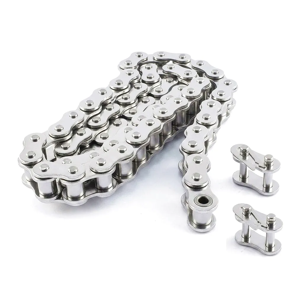
Customer Success Story: Rationalising Chain Selection at a Leeds Steel Fabrication Plant
A mid-sized structural steel fabrication business near Leeds had been experiencing frustratingly frequent chain failures on its roller conveyor drive systems — the lines responsible for moving cut and punched steel sections between fabrication stations. The plant’s maintenance records showed an average chain replacement interval of just 4–5 months across their seven most heavily loaded conveyor drives, each running 18-hour shifts six days per week. Total annual chain spend had reached a point where the operations director decided a full engineering review was warranted.
The plant’s mechanical engineer worked with Ever Power’s technical team to conduct a complete safety factor audit. The analysis began with direct measurement of chain velocities under operating load — rather than relying on the nameplate RPM of the drive motors. The results revealed that two of the seven conveyors were running at velocities 12–18% higher than originally designed due to gearbox changes made during a previous energy-efficiency upgrade. Combined with a Ks service factor of 1.5 (appropriate for the frequent stop-start loading characteristic of a fabrication line), the actual achieved safety factor on those two drives was calculated at just 4.8 — far below the 8.0 minimum recommended for this application class.
Ever Power recommended upgrading those two drives from ANSI 80 single-strand to ANSI 80 double-strand chain, which raised the effective breaking load by a factor of 1.7 (applying the ISO double-strand factor), increasing the calculated safety factor to 8.1 — just within specification. For the remaining five drives, the existing ANSI 80 single-strand chain was retained but upgraded to Ever Power’s premium shot-peened grade, which increased the verified fatigue endurance limit by approximately 25%. Post-upgrade monitoring over the following nine months recorded zero chain failures across all seven drives. The annualised chain expenditure fell by 68%, and the operations team gained the confidence to extend their planned maintenance intervals.
Case validated through plant maintenance log data and procurement records provided by the client. Identity details anonymised at client request.
What Our UK Clients Say About Ever Power Chain Performance
“We had been sourcing ANSI 100 chain from three different distributors with wildly inconsistent breaking-load performance on test. Ever Power’s batch certificates gave us actual tensile figures per production run — exactly what we needed to run our safety factor calculations with real confidence rather than catalogue assumptions. The chains have been running 11 months without a single failure.”
“We needed a custom drive chain for a new aggregate screening installation in the Pennines — non-standard pitch, specific attachment profiles, and a minimum breaking load target derived from our in-house safety factor calculation. Ever Power turned around a full technical proposal within 48 hours, including a suggested chain specification and a pre-production sample plan. The fabrication quality matched the spec precisely.”
“The Ever Power technical team walked us through the safety factor recalculation when we were upgrading our conveyor drive from a 15 kW to an 18.5 kW motor. Rather than simply upselling us a heavier chain, they showed us we could retain our existing ANSI 80 chain by upgrading to a double-strand configuration — saving us stock rationalisation headaches and keeping our spare-parts inventory simpler. That kind of honest advice builds long-term supplier relationships.”
Frequently Asked Questions: Roller Chain Safety Factor Calculation
Answers to the questions UK engineers and procurement teams ask most — written for clarity, not just search engines.
For general industrial conveyor applications in the UK running with smooth, uniform loading and adequate lubrication, the minimum recommended safety factor is 7.0 against the chain’s rated minimum tensile (breaking) strength. If the application involves moderate shock loading — such as frequent starts under load or variable feed rates — this rises to 10.0. For heavy, erratic shock loads typical of aggregate, mining, or primary metalworking applications, a minimum of 12.0 is widely accepted industry practice, with some standards bodies recommending up to 15.0 for the most severe service conditions.
Start by determining your nominal design power and applying an appropriate service factor Ks — for a steel plant with heavy shock loads, Ks values of 1.5–2.0 are typical. Multiply nominal power by Ks to get design power, then convert to effective chain tension using chain velocity. Add centrifugal tension if operating above 3 m/s. Divide the chain’s certified minimum breaking load by this total working tension to obtain Sf. For steel plant conditions near Sheffield, also apply a thermal derating factor if sustained ambient temperatures exceed 50°C. The resulting Sf must exceed your minimum recommended value for that application class — typically 10–12 for shock-loaded steel industry drives.
Ever Power provides batch-level material certificates and tensile test reports with all supply consignments, covering minimum and actual breaking loads, chemical composition of base steel, and heat treatment confirmation. These documents are suitable for inclusion in machinery technical files under UK machinery regulations post-Brexit. Contact [email protected] with your chain specification and the certifications required, and our technical team will confirm document availability before order placement.
Pricing for high-strength OEM-specification roller chains such as the 120HSP-00 and C100HSP-00 grades depends on the quantity ordered, the delivery port or destination, and any additional certification requirements. DDP pricing to UK ports is available and includes customs clearance and applicable duties. For an accurate quote, email [email protected] with your part number cross-reference (OEM number or application description), required quantity, and delivery location. Our UK-focused sales team typically responds within one business day.
Recalculation is warranted any time the drive operating conditions change meaningfully: motor upgrades that alter speed or power, gearbox ratio changes, modifications to the driven machine’s load profile, changes in ambient temperature or lubrication method, or any incident that suggests the existing chain may have been overloaded. In automotive plants in Birmingham, where JIT production pressures can tempt engineers to push equipment beyond its original specification, a routine safety factor audit every 12–18 months is prudent best practice — especially when the consequence of drive failure includes line stoppage costs.
The static safety factor compares peak working tension against the chain’s one-time tensile breaking load — appropriate for infrequent, non-repetitive loading. The dynamic safety factor compares the cyclic working stress against the fatigue endurance limit of the chain components, which is typically 15–18% of the breaking load. For any UK industrial application running continuous shifts — which describes the majority of manufacturing and processing environments in Birmingham, Leeds, Sheffield, and beyond — the dynamic (fatigue) safety factor is the critical design parameter, not the static one. A drive that looks adequate by static calculation may have a fatigue safety factor below 3.0, meaning failure within thousands rather than millions of cycles.
This article is produced by Ever Power’s technical content team for reference by mechanical engineers, plant managers, and procurement professionals in the UK and globally.
editado por gzl