Roller Chain Breaking Load vs. Working Load:
What Engineers Need to Know
A definitive engineering guide to understanding load ratings, safety factors, and chain selection for British industrial applications — from Birmingham’s automotive lines to Sheffield’s forging plants.
BS/DIN Standards
B2B Supply · UK Delivery
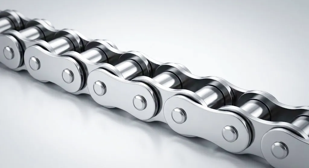
Every mechanical engineer working with chain drive systems in UK manufacturing environments — from the foundry floors of Sheffield to the automotive assembly lines of Birmingham and the heavy-process plants of Teesside — will at some point confront a critical distinction that determines whether a chain drive will perform reliably for years or fail catastrophically within weeks. That distinction is the difference between a roller chain’s breaking load (also called the minimum breaking force or tensile strength) and its working load (the permissible or safe working load). These two figures appear on every reputable manufacturer’s datasheet, yet the engineering logic connecting them — and the practical consequences of misunderstanding that relationship — deserves far more attention than it typically receives in procurement conversations. A roller chain that is selected purely on pitch and matching sprocket geometry, without a clear understanding of its actual load margins under dynamic operating conditions, is a roller chain waiting to fail under vibration, shock loading, or thermal fatigue. This guide cuts through the ambiguity and gives you the engineering clarity you need to specify correctly the first time.
Our engineering team responds within one business day. Custom specifications welcome.
What Exactly Is a Roller Chain’s Breaking Load?
Minimum Breaking Force (MBF)
The breaking load — formally called the Minimum Breaking Force (MBF) in ISO 606 and BS EN standards — represents the absolute tensile force at which a new, unlubricated chain will fracture under a steadily increasing static pull. This figure is measured in kilonewtons (kN) under controlled laboratory conditions using a tensile testing machine. The test applies a gradually increasing axial load until one link assembly ruptures. It is not a safe operating parameter. It is a material boundary — the point beyond which the chain’s structural integrity is permanently destroyed. In British standards practice, the MBF is the guaranteed minimum across a full batch of chains, meaning any individual chain in a compliant lot will meet or exceed this figure. Engineers in Coventry and Leicester working with automotive conveyor applications often reference this number as a maximum limit ceiling rather than an operational target, which is precisely the correct mental model.
Why This Number Alone Is Dangerous
A significant portion of chain failures in UK industrial sites occur not because engineers ignored the breaking load, but because they used it as a working reference without applying the appropriate safety factors. The breaking load is derived under static, single-direction, monotonically increasing tension — conditions that almost never exist on a live industrial drive. Real roller chain applications involve fluctuating loads, start-stop shock cycles, misalignment forces, temperature gradients, and the progressive fatigue accumulation that occurs over millions of load cycles. When a Sheffield steel plant’s conveyor chain fails at 60% of its rated breaking force after 18 months of service, the root cause is almost always a misunderstanding of dynamic working load principles rather than a defective product. The breaking load is the upper bound of a calculation, not the answer to it.
Understanding Working Load in Roller Chain Engineering
The working load of a roller chain — sometimes called the permissible working load, safe working load (SWL), or allowable tension — is the maximum tension the chain should experience during normal, continuous operation. Unlike the breaking load, which is a single static figure, the working load is a derived value that incorporates the application’s unique combination of speed, shock, lubrication, sprocket geometry, and environmental conditions. For any given chain, the working load will always be a fraction of the breaking load, and that fraction is determined by the safety factor appropriate to the application class.
In practice, the effective working load that a roller chain experiences is the sum of several tension components acting simultaneously: the tight-side tension transmitting the driving force, the centrifugal tension generated by the chain’s own mass at speed, and the catenary tension caused by the chain’s weight sagging on the slack side. For high-speed drives common in automotive production facilities across the West Midlands, centrifugal tension can account for a surprisingly large proportion of the total chain load, often exceeding 15–20% of the tight-side tension at speeds above 8 metres per second. Engineers who calculate only the tight-side tension based on transmitted torque will consistently underestimate the actual load and will be puzzled when their chain fatigues prematurely despite appearing to be well within the rated working load.
The relationship between the working load and the breaking load is formalised through the concept of the design safety factor (sometimes denoted as S or Sf in engineering literature). For a standard roller chain in a smooth, uniform-load application with good lubrication — the theoretical ideal rarely found in real manufacturing environments — ISO standards suggest a minimum safety factor of around 7:1. That means the working load should not exceed approximately 14% of the breaking load. In practice, UK manufacturing engineers typically apply higher safety factors of 10:1 to 15:1 for duty cycles involving impact, frequent starts, and contaminated environments, and factors of 20:1 or greater for life-critical or mining applications where chain failure could endanger personnel.
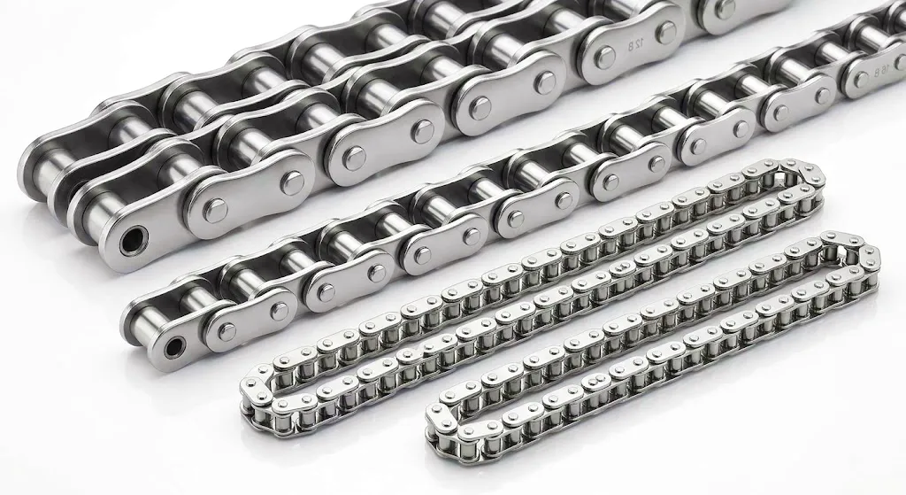
Core Engineering Formula
Where С = safety factor, F_break = minimum breaking force (kN), F_working = effective working tension (kN). Industry minimum: S ≥ 7 for smooth drives; S ≥ 15 for heavy shock applications.
Roller Chain Technical Performance Parameters
The following table consolidates the key performance and specification parameters engineers need when comparing roller chain grades for industrial applications in the UK. All values follow ISO 606 / BS EN standards and are indicative of quality manufactured chains such as those produced by Ever Power.
* Working loads shown are for smooth-drive, well-lubricated conditions. Apply appropriate service factors for shock, speed, and lubrication quality per ISO 10823.
Dynamic Load Factors That Every Drive Engineer Must Apply
Calculating the effective working load on a roller chain requires more than dividing the transmitted power by speed to get a tight-side tension figure. Real industrial drives — the kind found running continuously in the paper mills of Aberdeen, the packaging lines of Leeds, or the aggregate processing plants of the Midlands — impose a constellation of additional forces that must be accounted for if the chain selection is to be genuinely conservative and reliable. ISO 10823 provides a structured methodology for applying service factors, and understanding the reasoning behind those factors is essential for any engineer who wants to move beyond rule-of-thumb selection and into evidence-based mechanical design.
⚡ Shock Load Factor (Ks)
Applied based on the characteristics of the driving and driven machines. Smooth drives (electric motor to centrifugal pump) use Ks = 1.0. Moderate shock (geared motor to conveyor with uneven loading) uses Ks = 1.25–1.5. Heavy shock (diesel engine to crusher or hammer mill) demands Ks = 1.75–2.5. Misapplication of this factor is the single most common cause of premature chain failure in UK heavy industry.
📉 Lubrication Factor (Kl)
Chain performance is profoundly sensitive to lubrication quality. A chain operating with full oil bath lubrication can handle significantly higher working loads than the same chain running dry or with manual drip lubrication. The lubrication factor Kl ranges from 1.0 (oil bath, perfect conditions) to 1.5 (manual or minimal lubrication) to 3.0 or more for dry, contaminated, or hostile environments. In food processing or pharmaceutical facilities where petroleum lubricants are prohibited, this factor drives chain selection decisions substantially toward heavier-rated products.
📈 Speed Factor (Kv)
As chain speed increases, so does the centrifugal tension component. The speed factor effectively reduces the available working load margin. At chain speeds above 5 m/s, the centrifugal tension begins to represent a meaningful fraction of the allowable working load. The power rating tables published by ISO and quality manufacturers like Ever Power already account for centrifugal effects at rated speeds, but engineers must recalculate when operating at speeds outside the tabulated range. Drive trains running in variable-speed applications — common in modern VFD-controlled production lines — require analysis at both minimum and maximum speeds.
◀ Sprocket Tooth Factor (Kz)
Standard power ratings are calculated for a 19-tooth sprocket. Smaller sprockets create higher polygon effect — the geometric variation in chain velocity that occurs as each link engages and disengages — resulting in higher impact loads per tooth and elevated pin-bush contact pressures. The tooth factor Kz penalises small sprocket counts (below 17 teeth) and rewards larger sprockets. For drives where space constraints force the use of sprockets with fewer than 15 teeth — not uncommon in compact gearbox-driven systems in the aerospace manufacturing facilities of Bristol — the working load must be derated significantly.
Roller Chain Construction: Working Principle and Core Materials
A roller chain transmits mechanical power through an elegantly simple mechanism: the chain wraps around toothed sprockets, and as the driving sprocket rotates, it pushes against the chain rollers, which engage successive teeth on the driven sprocket. The discrete engagement of each link creates a positive, non-slip drive with a fixed velocity ratio — something no belt drive can guarantee — making roller chain the preferred power transmission solution for applications where synchronised motion or precise speed ratios are essential. Understanding how the load distributes through this mechanism at the component level is the key to appreciating why breaking load and working load must be considered as distinct engineering concepts rather than interchangeable terms.
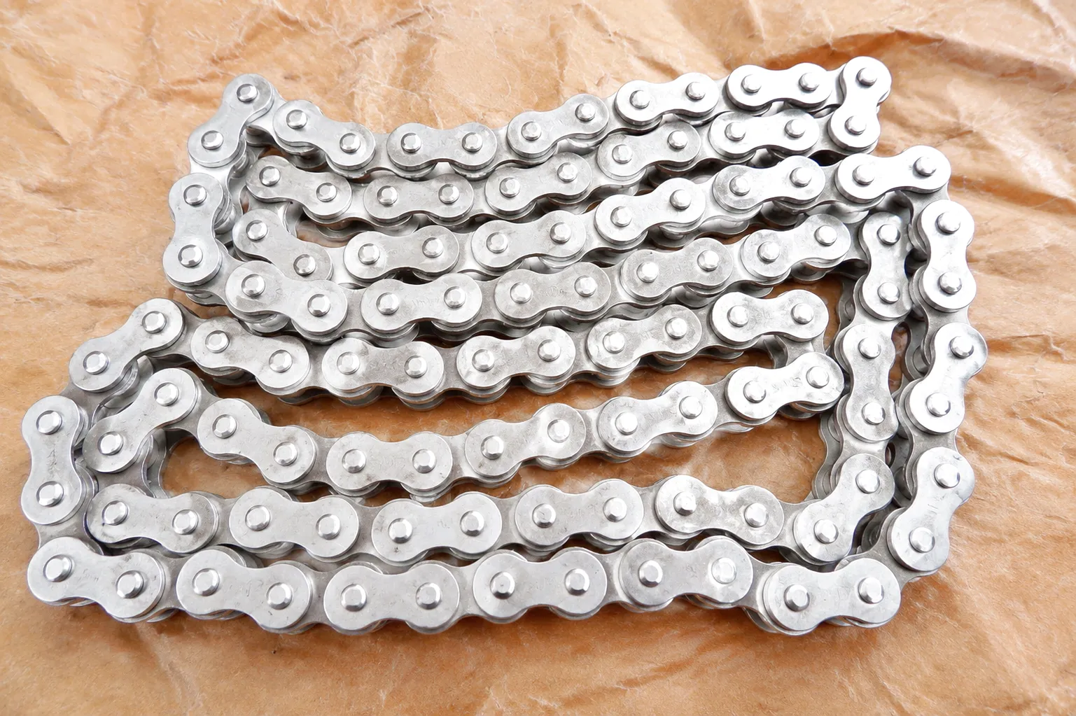
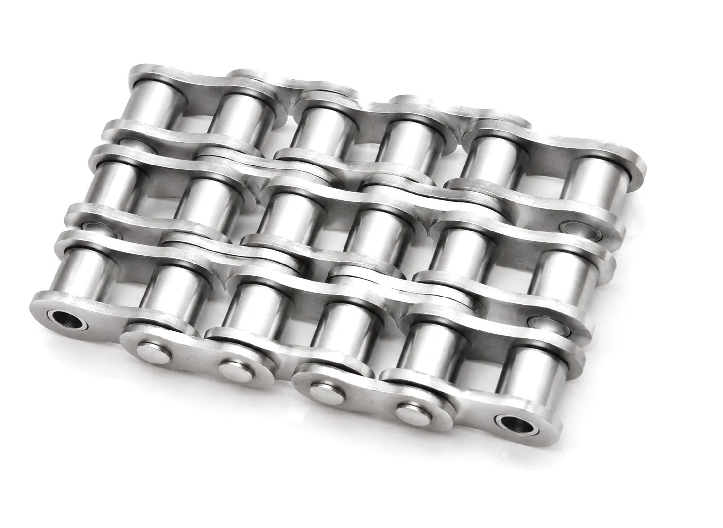
The load path through a roller chain under tension runs through the outer link plates, through the outer link pins, through the bushings (which rotate against the pins), and through the rollers (which engage the sprocket teeth). Each of these components is a potential failure mode, and the material choices for each are carefully engineered to balance tensile strength, fatigue resistance, wear resistance, and toughness. The outer and inner link plates are typically cold-stamped from medium-carbon or alloy steel strip, heat-treated to achieve Rockwell hardness values in the range of HRC 40–48 for standard roller chain. High-strength variants — such as the heavy-duty chains designed for Caterpillar-compatible applications — use higher-alloy plate steels with tensile strengths exceeding 1000 MPa to achieve the elevated breaking loads required in earthmoving and mining equipment.
The pins represent the most critically loaded component in the chain assembly. In standard industrial roller chain, pins are manufactured from medium-carbon steel that has been carburised and case-hardened to create a hard, wear-resistant outer shell over a tough, ductile core — the same engineering logic that governs the design of gear teeth and bearing raceways. The bushing material, particularly in heavy-duty and high-speed applications, is typically sintered or solid steel, precision-bored and press-fitted into the inner link plates. The rollers, which absorb the shock of sprocket tooth engagement, are heat-treated to a surface hardness of approximately HRC 58–64, balancing hardness with sufficient toughness to resist fracture under impact loading. For corrosion-resistant applications, stainless steel (typically 316L or 304 grade) is specified throughout, at the cost of some reduction in tensile strength compared to carbon steel equivalents.
Соединительные пластины
Medium-carbon or alloy steel; HRC 40–48; cold stamped, heat treated; high-tensile variants exceed 1000 MPa UTS
Булавки
Carburised carbon / chromium-moly steel; case-hardened outer shell; tough ductile core; precision ground to h6 tolerance
Bushings & Rollers
Sintered or solid steel; rollers HRC 58–64; press-fit precision; optional 316L stainless for corrosive environments
High-Strength Roller Chain Products for Caterpillar Applications
Certain application environments — earthmoving, mining, construction equipment — demand roller chain specifications that go well beyond the standard ISO 606 performance envelope. Ever Power has developed a series of high-strength roller chains specifically engineered to meet and exceed OEM requirements for Caterpillar equipment, where the combination of extreme shock loads, abrasive contamination, and high ambient temperatures creates service conditions that ordinary industrial chain cannot withstand reliably. These are chains where the gap between working load and breaking load is intentionally designed to be large, because the application’s real working loads vary dramatically and unpredictably.
Industrial Application Scenarios: UK Manufacturing and Heavy Industry
Roller chain drives are embedded in the operational fabric of British industry, from the North Sea oil support equipment fabricated in Aberdeen to the food packaging lines of the East Midlands and the port handling equipment running continuously at Felixstowe and Southampton. Each application brings its own unique combination of load character, speed range, environmental conditions, and maintenance access constraints — factors that directly govern how the relationship between breaking load and working load must be interpreted.
🏭 Automotive Manufacturing (Birmingham / Coventry / Derby)
Engine timing chains, camshaft drives, and conveyors in body-in-white assembly lines represent applications where the working load is relatively modest but where precision, consistency, and chain fatigue life over millions of cycles are paramount. A chain that operates at 25% of its breaking load but accumulates 10 million load cycles per year requires fatigue-rated selection methodology, not just static load comparison. The uniform load character and good lubrication conditions in automotive plants typically allow the application of moderate service factors, but the demanding cycle counts call for chains with excellent surface finish on the pin and bush bearing surfaces to minimise wear-driven elongation.
⛭ Steel and Metals Processing (Sheffield / Rotherham / Scunthorpe)
The steel towns of South Yorkshire still run substantial chains in walking beam furnaces, billet transfer conveyors, and rolling mill auxiliary drives. These environments combine high ambient temperatures, abrasive scale contamination, and heavy shock loads — precisely the conditions that demand the most conservative application of safety factors. Roller chains in Sheffield mill environments are frequently specified with working loads representing only 5–7% of the breaking load, not because the ISO minimum requires it, but because the inspection intervals are long and the consequence of an unplanned chain failure — line shutdown, personnel risk, reheated billet scrap — is commercially devastating.
🏧 Food and Beverage Processing (Leeds / Northamptonshire / East Anglian Facilities)
Food processing chain applications introduce the additional complexity of wash-down environments, restricted lubricant options (NSF H1 food-grade lubricants have lower film strength than industrial oils), and regulatory requirements that prohibit carbon steel in contact with food products. Here, stainless steel roller chain or ANSI/ISO chain with NSF-approved coatings is mandatory, and the reduced mechanical properties of austenitic stainless must be factored into the working load calculation — typically a 20–30% reduction in breaking load compared to alloy steel equivalents. Drives in chilled storage environments also contend with lubricant viscosity changes that affect film formation and pin-bushing contact conditions.
⚒ Mining and Quarrying (Derbyshire / Welsh Coalfield Region / Scottish Highlands Aggregate)
Mining drives represent the most extreme end of the roller chain application spectrum. Armoured face conveyors, shearer haulage systems, and crusher drives operate under load profiles that include frequent overloads, shock events from rock jamming, and abrasive contamination from coal dust and silica particles. These are the applications where high-strength heavy series chains with breaking loads several times that of standard pitch chains are selected, and where working loads are set at margins that provide genuine protection against the unexpected loading spikes that inevitably occur during normal mining operations. UK coal and aggregates operations across Derbyshire and the Welsh borders rely on chain reliability as a fundamental safety constraint, not merely a production efficiency metric.
✈ Aerospace and Defence Manufacturing (Bristol / Preston / Portsmouth)
Aerospace manufacturing facilities demand chain precision, traceability, and documentation that goes beyond the requirements of most other UK industries. Engine test cell drives, component finishing conveyors, and jig positioning systems use precision roller chain where the tolerance on pitch and straightness is a critical quality parameter alongside the load ratings. In facilities like those operating in Bristol’s aerospace corridor or the defence manufacturing plants of Portsmouth, chains are often specified with full material certifications, heat treatment records, and dimensional inspection reports — the supply chain documentation that Ever Power provides as standard for customers requiring full material traceability.
🚪 Port and Logistics Handling (Felixstowe / Southampton / Liverpool)
Container handling equipment, ship-to-shore cranes, and conveyor systems at UK ports operate under conditions of high utilisation, salt air corrosion, and variable ambient temperatures across the full British seasonal range. Roller chains in port environments are typically specified with marine-grade surface protection treatments or stainless materials, and the working load must account for the high starting loads that occur when conveyor systems are started fully loaded — a shock condition that can momentarily impose 2–3 times the steady-state tension on the chain assembly. Port operators sourcing chain for Felixstowe or Liverpool facilities consistently require fast ex-stock dispatch capability, which is something Ever Power’s UK supply network is positioned to support with standard B-series chain available for next-day delivery.
Ever Power: Precision Chain Manufacturing and Customisation
Ever Power operates a dedicated roller chain manufacturing facility equipped with CNC precision machining centres, automated heat treatment lines, and multi-axis CMM inspection equipment — the industrial infrastructure required to produce chain that performs consistently at both ends of its rated load range. The facility’s quality management system is certified to ISO 9001, and our heat treatment processes for chain pins and plates are validated against documented metallurgical specifications that control case hardness depth, core hardness, and microstructure. This is not specification-to-catalogue supply; it is engineered manufacturing with a direct connection between process parameters and the mechanical performance properties that define both breaking load and working load.
Customisation is not a secondary service at Ever Power — it is a core competency. UK industrial customers regularly approach us with requirements that fall outside the standard catalogue range: non-standard pitches, modified attachment plates, extended or shortened pin ends, special surface treatments for high-temperature or corrosive environments, and custom breaking load certifications for applications covered by Machinery Directive safety documentation. Our engineering team works directly with customer engineers to develop a chain specification that addresses the true application requirements rather than defaulting to the nearest off-the-shelf product. For British OEMs designing new machinery, this collaborative approach means the chain specification can be integrated into the design process from the outset, rather than being retrofitted to a drive geometry that was designed around a catalogue product.
Our supply chain reliability is particularly important for UK manufacturing customers operating just-in-time production schedules. We maintain substantial stockholding of standard B-series and A-series roller chain in both simplex and multiplex configurations, enabling short lead times for standard orders. For custom specifications, our production planning team provides realistic lead time commitments and can support customers with bridge stock from near-equivalent standard products during the production run of bespoke items. Full material certifications, dimensional inspection reports, and fatigue test data are available on request for applications requiring documented chain performance.
Request a Custom Roller Chain Quote
Share your application requirements — pitch, working load, breaking load target, environmental conditions — and our engineering team will respond with a tailored specification and commercial offer within one business day.
Chain Elongation, Fatigue, and the Practical Limits of Working Load
Even when a roller chain is operating well within its working load limit, progressive wear elongation is inevitable. As the bearing surfaces of the pins and bushings wear, the effective pitch of the chain increases slightly — a phenomenon measured as percentage elongation across a defined number of links. Standard practice across UK maintenance engineering is to replace chain when elongation reaches 2% for small sprockets or 3% for larger sprocket diameters, at which point the chain can no longer correctly engage the sprocket tooth profile and the resulting “riding up” of the chain on the sprocket teeth dramatically increases the tensile loads experienced by individual links, effectively reducing the safety margin between working load and breaking load at each engagement point.
Fatigue failure is the mode most commonly seen in chains that are technically within their working load but are running at the upper end of that range. The fatigue limit of a roller chain — the cyclic stress range below which the chain will theoretically survive an infinite number of load cycles — is typically around 15–25% of the chain’s breaking load for quality manufactured chain in good condition. When working loads consistently approach or exceed this fatigue limit, even momentarily during shock events, the cumulative damage accumulates in the press-fit interface between pin and outer link plate, in the pin shear zone, or in the link plate root radius region. Fatigue cracks in these locations are microscopic in their early stages and often invisible during routine visual inspection, which is why chains in high-duty UK applications are best monitored using elongation measurement rather than visual assessment alone.
The practical implication for engineers is that the working load limit must be understood as a continuous operating ceiling, not a momentary maximum. A chain that briefly exceeds its working load during a shock event but operates nominally below it in steady state is accumulating fatigue damage at a rate that will shorten its service life relative to a chain that remains genuinely within its design margin at all times. For UK plant maintenance teams working on Planned Preventive Maintenance (PPM) schedules — common practice in the automotive, pharmaceutical, and food processing sectors — understanding this distinction allows inspection intervals to be calibrated to the actual duty severity rather than applying a single blanket replacement interval regardless of application conditions.
Customer Success Story: Rotherham Forging Plant Eliminates Unplanned Downtime
A mid-size precision forging plant in Rotherham — part of the wider South Yorkshire metals cluster supplying the UK automotive and aerospace supply chains — had been experiencing a pattern of roller chain failures on their transfer conveyor system that moved forged billets between the furnace charge and the press stations. The chains were being replaced every four to six months, generating significant unplanned downtime costs estimated at £18,000–£24,000 per incident when press idle time, billet scrap, and overtime labour were aggregated. The plant’s engineering team had been selecting chain from a distributor catalogue based purely on pitch and nominal working load, without applying service factors for the shock loading generated by billet drops onto the chain conveyor or the elevated temperature in the transfer zone.
Ever Power’s technical sales team conducted a detailed application review, including calculation of the effective working load with appropriate shock factors (Ks = 1.75, reflecting the heavy shock of billet loading), a temperature derating factor for the elevated ambient conditions near the furnace exit, and an elevated safety factor target of 12:1 to reflect the plant’s desire to achieve a 12-month minimum chain life to align with their annual planned shutdown schedule. The review showed that the chain specification in use was operating at effective working loads that represented over 20% of the chain’s breaking load — well beyond the fatigue limit of the standard grade being used. Ever Power recommended a transition to a heavy-series roller chain with a significantly higher breaking load, combined with an upgraded lubricant delivery system and a revised sprocket arrangement that increased the small sprocket tooth count from 13 to 17 teeth.
Following implementation, the plant ran for 14 consecutive months without a chain failure on the modified conveyor. The engineering team conducted a formal post-implementation review and confirmed that the elongation measurement at month 14 was at 1.6%, well within the 3% replacement threshold — indicating the chain could confidently have been run for a further two to three months before replacement became necessary. The total maintenance cost saving in the first year post-implementation, compared to the previous four years’ average, exceeded £65,000 when all downtime, labour, and material costs were accounted for. The plant’s maintenance manager subsequently extended the same load analysis methodology to three other chain drive applications on site.
Customer Reviews
“Ever Power’s engineering team spotted immediately that we were running at nearly three times what the chain could sustain in fatigue terms. The custom heavy-series specification they recommended has run for over a year with no issues — exactly what we needed on a safety-critical transfer line. The full material certificates they provided also satisfied our customer’s auditor requirements without any back-and-forth.”
“We supply conveyor systems to UK port operators and Ever Power has become our preferred chain supplier for high-load applications. Their ability to provide custom attachment plates and non-standard pitch modifications to a tight lead time has been a genuine differentiator for our business. The breaking load consistency across batches is notably better than what we were getting from our previous supplier — our quality team has the data to prove it.”
“The Caterpillar-compatible high-strength chain from Ever Power has performed well beyond what the OEM replacement parts achieved in our aggregate processing equipment. We’re running in a high-dust, heavy-shock environment in Derbyshire, and the chain has now exceeded 16 months of service compared to the 8–10 months we were getting previously. The price point is also genuinely competitive — getting a quotation was straightforward and the technical specifications were clear and traceable.”
Practical Roller Chain Selection Checklist for UK Engineers
✅ Step-by-Step Selection Process
Calculate tight-side tension from transmitted power and chain speed. Do not overlook centrifugal tension at speeds above 5 m/s.
Apply the shock service factor Ks based on the driving and driven machine combination per ISO 10823 classification tables.
Apply lubrication factor Kl. Reduce the allowable working load if lubrication is minimal, intermittent, or food-grade restricted.
Check small sprocket tooth count and apply tooth factor Kz for sprockets below 17 teeth. Consider redesigning for larger sprockets where space allows.
Select a chain whose catalogue working load exceeds the corrected effective load. Verify that the effective load is below the fatigue limit (typically 15–25% of breaking load) for high-cycle applications.
Confirm the overall safety factor (breaking load divided by effective working load including all service factors) meets the minimum requirements for your application and any applicable safety regulations under UK PSSR 2000 or Machinery Regulations 2008.
⚠ Common Specification Errors
- Using breaking load as the working load ceiling without applying any safety factor
- Ignoring centrifugal tension in high-speed calculations
- Applying smooth-drive service factors to shock-loaded applications
- Selecting chain pitch and grade from speed-power charts without verifying actual safety factor
- Failing to account for reduced lubrication effectiveness in high-temperature zones
- Ignoring chain elongation as a condition indicator, relying solely on visual inspection
Frequently Asked Questions
Common questions from UK engineering professionals and procurement teams about roller chain load ratings, pricing, and supply.
Ever Power Roller Chain
Precision Chain Manufacturing · ISO 9001 Certified · UK B2B Supply
отредактировано gzl